Digital Stopwatch Assignment
- Country :
Australia
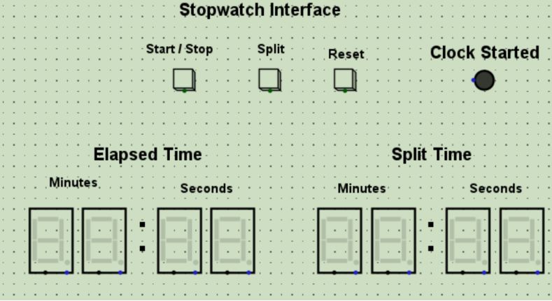
For this assignment, you are going to implement the functionality for a simple stopwatch interface as shown above. The interface itself is already provided as a Logisim file named main.circ . Your assignment must be built using this file as the interface. You are encouraged to use multiple circuits to implement specific components however your whole circuit must be operable and displayed using the buttons and display components in this file. That is, your solution should not require any additional interface components (e.g., buttons, displays, pins etc) in order to test the functionality of your circuit.
Logisim Version
Your assignment must be implemented using Logisim Evolution 3.8.0, which can be downloaded from: https://github.com/logisim-evolution/logisim-evolution/releases This is the version we will test with, and we will not be using any other version, or making special accommodations. If your solution is incompatible with ours, it will not be able to be tested and thus will be ineligible for most marks on offer.
You can verify that your version is correct by loading the provided main.circ file with the interface as shown above.
Allowable Logisim Components
Only the following components may be used to develop your solution:
- Logic Gates: any
- Flip Flops: JK, D, S-R, T
- LEDs
- Clock (only one)
- Hex Digit Display (already provided in interface)
- Buttons (already provided in interface)
- Pins (for connecting circuits)
- Constants (for setting inputs that will not change)
- Splitter (for using HEX Digit Display)The use of any other components will be penalised in particular, you must not use any pre-built circuits such as registers, shift registers, etc).
Assignment Stages
To break the problem down, you will implement the functionality of the stopwatch in stages. Each stage has a percentage weighting of marks contributing to the overall total of 100% You should implement each stage in order, and upon completion of each stage, save your file using the naming convention: stageX.circ.
This assignment will take a long time to complete in full. You should start early and work methodically through each stage. Note however that a good mark for this assignment does not require all stages being complete. In particular, Stages 6 and 7 are considered more advanced,
Stage 1: Implement the Start/Stop button (10% of total marks)
Using the Start/Stop button provided in main.circ, wire up a simple circuit that toggles between the Start and Stop states every time the button is clicked. Your solution should:
rt and Stop states every time the button is clicked. Your solution should:
- Use the Clock Started LED and ensure it is turned on when in the Stopwatch is in the Start state, and off when in the Stop state,
- Make use of a Flip Flop to keep track of the current state.
Stage 2: Implement a single digit Seconds display (15% of total marks)
This stopwatch will provide 1 second precision, and so needs to display the number of seconds that have elapsed since the Start button was pressed. As such, this will require the implementation of a counter. You will start by implementing a single digit Seconds counter for the units column of the Seconds display. That is, a counter that increments the Seconds display by 1s every clock tick, between 0 and 9. Specifically:
- Replace your flashing LED in Stage 1 with a counter that keeps track of the number of seconds (in increments of 1s, between 0s and 9s).
- The Seconds display should start from 00 when the Start/Stop button is first pressed
- The Seconds display should Stop when the Start/Stop button is pressed in the Start state.
- The Seconds display should resume counting when the Start/Stop button is pressed in the Stop state
For this stage you can assume a single clock pulse equals 1s, and the display will only show the units column in seconds. As such, your Seconds display should only show values: 00, 01, 02, 03, 04, 05 09, and then wrap back to 00.
Stage 3: Implement the full two-digit Seconds display (20% of total marks)
Youre now going to implement full Seconds display for your stopwatch. Modify your circuit so that:
- the seconds display now shows Seconds in 1s increments using both the units and tens column. That is, the display will now show values: 00, 01, 02 . 57, 58, 59, and then wrap back to 00.
- the display resets to all zeros whenever the Reset button is clicked, and enters the Stop state (i.e., the Elapsed Time remains 00:00).
- Your circuit should explicitly ensure no illegal values are displayed (e.g., no hex values displayed or digits above 5 in the tens column, etc).
Stage 4: Implement the Minutes display (15% of total marks)
In this stage you will implement the remaining time display components (i.e.., Minutes). These are described in two sub-stages below. Implement a Minutes display using the two hex digit displays labelled Minutes. Specifically, your Minutes display should:
- display decimal values only from 00 to 99, and then wrap back to 00
- only increment when the Seconds display is wrapping back to 00 (and this should be at the same time).
- ensure the Start/Stop and Reset buttons work for the Minutes display as they do for the S
Stage 5: Implement the Split button (15% of total marks)
Most stop watches provide a Split button that allows intermediate times (i.e., lap times) to be recorded and displayed. In this stage you will implement the Split display. For this you will use the second Split Time display as shown on the Interface above to show the stopwatch time at the time the Split button is pressed.
Specifically, your circuit should:
- display the elapsed time on the Split Time display at the moment when the Split button is pressed, and only when the stopwatch is not in the Stop state
- Ensure the displayed Split time remains displayed and unchanged until the next time Split is pressed, or the Reset button is pressed.
- If the Reset button is pressed, the Split Time display should read 00:00
Note that the Split button should not impact the Elapsed Time display. It should continue to count as normal.
Stage 6: Implement Split time recording and multi-Split display (15% of total marks)
It is often useful to be able to see each Split time recorded (e.g., the time of each lap completed) upon completion of a timed activity. In this stage you will implement the logic required to record up to 5 separate Split times during a single timed activity. In addition, you will implement a feature allowing the user to view each split time in turn on the Split Time display, when the stopwatch is in the Stop state.
Part 6A:
When the stopwatch is active (i.e., not in the Stop state), your circuit should: (10% of marks)
- record the current Split time when the Split button is pressed
- ensure up to the last 5 split times remain recorded (if more than 5 split times are recorded, it should forget the earliest split time to make room).
- It must use Flip Flops to implement the storage.
- Ensure the most recent split time is displayed on the Split Time display at all times
- Set all recorded split times to 0 when the Reset button is pressed
- Provide Hex Digit Displays to verify the contents of each time being stored (this should be separate from the main interface but obvious for markers to find).
Part 6B:
When the stopwatch is in the Stop state (i.e., not currently timing an activity): (5% of marks)
- Ensure the most recent split time is displayed at the moment the Stop state is entered
- Show each split time in turn on the Split Time display, when the Split button is pressed. That is, when the Split button is pressed, your Split Time display should move to the next split time recorded
- Ensure the Split Time display wraps back to the earliest recorded split time after showing the most recent split time (when the Split button is pressed).
Stage 7: One Display for Everything (10% of total marks)
In this final stage you will display all times using only the Elapsed Time display. That is, Split times will also be shown on the same display when the stopwatch is in the stopped state, and the Split button is pressed.
Specifically:
- The display of Split Times will work exactly the same was as described in Stage 6, but using the HEX Digit displays used for Elapsed Time.
- In addition to the last 5 recorded split times, your display should also show the Elapsed Time at the time the Stop button was pressed, and by default, if no Split time was recorded when the stopwatch was last active, then the Elapsed Time should remain showing the Elapsed Time last recorded.
- If the Start button is pressed after being in the Stop state, the display should switch back to showing the elapsed time, the stopwatch should start keeping time again.
- If no Split time was recorded and the Split button is pressed, it should just show 00:00.
- For this stage, you should also add an additional LED to indicate when a Split time is being displayed. The LED should not be on when showing the Elapsed Time.
