Panel method Assignment
- Subject Code :
MCEN90018
- Country :
Australia
Assignment 2 - Panel Methods
This assignment should be done in groups of 2 students. Both stu- dents in the group will get the same mark for this assignment. If you choose to do the assignment alone, no concession will be given. Your assignment will be marked the same as an assignment done by two students. Assignment to be handed in by midnight Sunday 1st May 2022. Please include all figures and answers, as requested below, and sufficient explanation such that I can follow your reasoning. When submitting, please also attach codes for each question (except for question 3).
For this assignment, you are going to produce your own simple source panel code, and then modify this to the vortex panel technique.
- First step: lets get a code working for something that we already know the answer to. Produce a source panel code for solving an eight panel cylinder as shown in the set of The cylinder has radius a = 1m, and the background flow is horizontal from left to right with U? = 1 ms?1. Plot the colour contours of u component of velocity and streamlines starting from x = ?3, y = ?2 : 0.25 : 2. This first part should look verysimilar to figure 10 from these notes. Use different colours (i.e colormap(parula)) to reassure me that you have not cheated. Set your color axis limits between 0 < U>2.5(caxis([0 2.5])). (10 Marks)
- Calculate the pressure coefficient Cp from the tangential velocity component at the midpoint of the 8 Compare this to the theoretical solution (as a plot of Cp vs ?). (10 Marks)
- Repeat parts 1 and 2 for a 64 panel cylinder (include plots - but do not include code for this part). (5 Marks)
- Now that you are confident that your panel code is working, deploy your source panel code to some different and more exciting Plot the resulting flow-field and discuss. (interesting features? any problems / shortcomings?) (10 Marks)
- Now modify your code to a compute a vortex panel solution of the cylinder with zero rotation (with a = 1 m and U? = 1 ms?1). Start initially with a 64 panel cylinder. You now need to satisfy the Kutta condition at ? = 0?. Plot the colour contours of the u component with overlaid streamlines (with same starting points as in part 1). Also plot the Cp distribution (Cp vs ?). Compare with the source panel solution from Part (20 Marks)
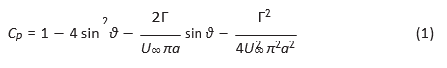
- Now modify you vortex panel code to simulate a rotating cylinder with ? = 2U??a. Compare your vortex panel solution to the theoretical potential flow solution (dou- blet + uniform flow + potential vortex) by plotting colour contours of the u compo- nent of velocity with overlaid streamlines and also by plotting the Cp distribution
(vs ?). A reminder from MCEN90008 that Cp for a rotating cylinder is given by,
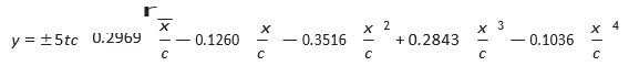
- Modify your code to produce a vortex panel solution to calculate the flow around a NACA0012 airfoil with a chord c = 1 at angle of attack ? = 10?. The coordinates for the NACA0012 airfoil are given by the following equation,
 (2)
(2)
where t = 0.12 (0010 series is a symmetric airfoil with t/c = 0.12). Assume U? = 1. Plot a similar figure to part 1. A colour contour plot of u with streamlines starting at x = -0.5, y = -0.5:0.0625:0.5. Show a red streamline that starts at the airfoil trailing edge to demonstrate that the Kutta condition has been satisfied. Set your color axis limits between 0.5 and 1.5. Set your axis limits ?0.5 < x>1.5 and ?0.5 < y < 0.5. Use colormap(jet) (10 Marks)
axis([-0.5 1.5 -0.5 0.5])
caxis([0.5 1.5] colormap(jet)
- Plot Cp vs x for the vortex panel simulated NACA0012 airfoil at ? = 10?. Also plot the lift coefficient vs angle of attack curve (Cl vs ?) for the airfoil (for the range ? = 0? to ? = 10? in steps of one degree). Comment on this curve - do you trust it? what will happen to your panel solution at higher angle of attack? (10 Marks)
- An aircraft with an all up weight of 200,000 Kg uses a wing with a NACA0012 cross It has a wing area designed such that it can cruise at 250 ms?1 at an altitude of 10,000 m (? = 0.4135 kg m?3) with an angle of attack of ? = 3?. Assuming that the stall angle angle for the NACA0012 is 10?, compute the minimum landing speed at sea-level (? = 1.225 kg m?3). Comment on what the aircraft designers could practically do to reduce the landing speed (without changing the wing area). (10 Marks)
