To prepare a roadmap to bulid electrical systems for a building
- Country :
Australia
Assignment Brief and Guidance
You are a technical engineer at an Institute, part of your duties is to build electrical systems that provide solutions to problems within the main building, and when possible, provide preventive measures to predictable faults
Wherever you are the letter K, it means the last two digits of your student number, for example if your student number is 17220013, then K is (13), there is no excuse for using a wrong number, Wherever you see the symbol S, it means the last digits of your student number, for example if your student number is 17220013, then 5 is (3), there is no excuse for using a wrong number.
Task 1
The first few weeks you've worked on number of circuits and devices to test the properties and characteristics of the operational amplifiers in multiple scenarios.
(1-a) Submit your work in a report style.
(1-b) Regarding the submitted logbook describe- in detail - the various types of amplifiers and their applications, and the effect of different performance characteristics of types of amplifiers.
(1-c) Explain the results obtained from applying practical tests on an amplifier's performance.
(1-d) Evaluate the results of practical and virtual tests to analyze the effect of feedback on an amplifier's performance.
Task 2
Check the block diagram below:
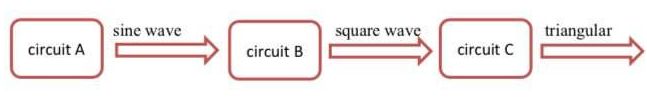
(2-a) Knowing that circuit A is a Wien bridge oscillator, its output is a sinusoidal wave with frequency defined by the following equation:
frequency 10* (K+10) Hz
design circuit A and show all steps of the design process, perform simulation to show the output (measure and record the magnitude and frequency of the simulated sine wave), then construct the circuit practically in the lab, measure the output's magnitude and frequency and plot the output Waveform
(2-b) Knowing that circuit B produces a square wave output, which has the same frequency the sine wave, design circuit B, perform simulation of both stages (circuits A and B) to show the square output, then construct both stages (circuits A and B) practically in the lab, measure of the magnitude and frequency of the square wave and plot the output waveform
(2-c) Knowing that circuit C produces a triangular wave output, which has the same frequency of the sine wave, design circuit C. perform simulation of all three stages (circuits A, B and C) circuit practically in the lab, measure the output's magnitude and frequency and plot the output waveform
(2-d) Talk about the characteristics and applications of Wien bridge oscillator.
(2-e) Talk about the characteristics and applications of crystal oscillator.
Task 3
(3-a) Design a dual DC power supply, SV DC and -5V DC, show all steps of the design process. The lab instructor will provide you with two voltage regulators (-5V and +5V voltage regulator ICs); as you apply those devices (voltage regulators) in the power supply circuit, refer to the manufacturer's specification sheets, and you MUST interpret relevant information from manufacturer's data, and relate this information to the measured values in your design.
(3-b) Simulate the designed circuits, plot and record the output.
(3-c) Construct the DC power supply circuits practically in the lab, measure, plot and record the outputs.
Task 4:
(4-a) Design a fourth order Butterworth High pass filter showing all steps of your design (including all calculations), the specifications of the filter are as following:

- The passband gain is 1
(4-b) Simulate the designed filter and plot the frequency response, measure, plot the cutoff frequency, the roll-off, and the passband gain.
(4-c) Construct the designed filter circuit practically in the lab, measure, plot and record the frequency response, measure the cutoff frequency, the roll-off, and the passband gain
Task 5:
Your team leader asked you to design, simulate and build an emergency alarm system,
A push button is placed in a corridor, when someone presses on the push button an audio alarm and a red LED are both turned on, and they stay on until someone presses the pushbutton again.
For this circuit you will be provided with a 5V magnetic buzzer (for the audio alarm), an LED, a push button and all the passive components which you may need.
Show all steps of the design process, simulate the circuit and plot the outputs of all stages, build the circuit in the lab and plot all outputs.
Task 6:
(6-a) For all the previous tasks (tasks I to 5), you are required to explain the obtained results, assess and analyze those results, and evaluate the performance of the tested circuits. Same applies to electronic devices. Make sure that identifying proper devices and IC's should be justified and combined with proper interpretation of datasheets as to what relates to the required operation.
(6-b) Submit all practical circuits to the lab supervisor,
