ELEC 4100 Electrical Energy Systems
- Subject Code :
ELEC-4100
- Country :
Australia
Question 1.
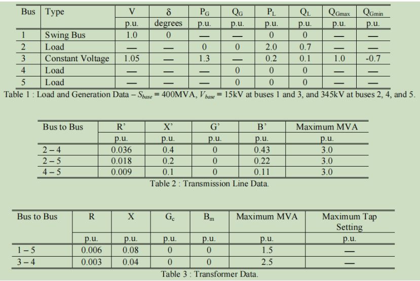
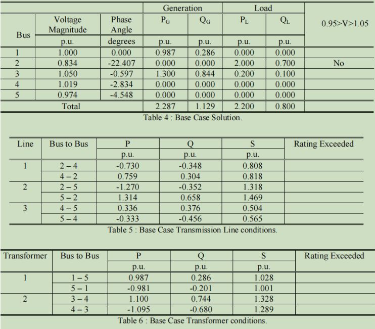
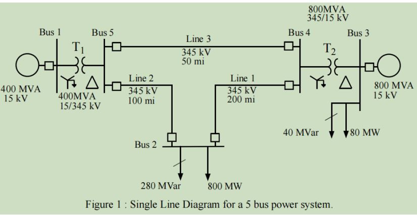
Figure 1 shows a single line diagram of a five bus power system. Input data for the network are given in the tables on page 2. Note that the data given for this system are calculated on a 400MVA base. The Power World simulator by default works on a 100MVA base. There are two possible approaches to account for this. First it is possible to change the default base setting, or the MW and Mvar loads in figure 1 can be divided by four. For the latter approach, explain the division by four.Use the Power World simulator to determine the base case solution given on page 2. What are the real and reactive power losses for the system.
Question 2.
What happens to the voltages, line flows, and real power losses when a 50Mvar capacitor is connected to bus 2? Why do the real power losses change in this way? What size shunt capacitor bank would be required at bus 2 to increase V2 to 1.0 p.u.
Question 3.
Install an additional line from bus 2 to bus 4. The line parameters of the new line equal those of the existing line 2-4. Determine the effect on V2, on the line loadings, and on the total I2R losses.