Electromagnetic, Antennas And Propagation Assignment
- Country :
Australia
Introduction
Most real-life electromagnetic problems do not fall into a class that can be solved by analytical methods. For these common situations, we must resort to numerical approximate solutions [1]
Numerical methods are becoming ubiquitous in engineering practice as digital computer speed and memory capacity continue to increase. Among the powerful methods are those using finite differences (FD), finite elements, or methods of moments [2],[3]. The students are referred to the Lectures on "Numerical Methods and references therein for further details about different methods and commercial software.
Assignment
Task 1
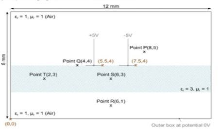
Write a computer program to implement the FD method that will solve the scenario shown in the figure. Notice that the potential difference between the 1 mm width central metal plates resting over a suspended 2 mm thick dielectric slab is +10V and the rest of the metal boundaries are at potential OV. If the structure extends into the page, it is known as a shielded suspended differential line or co planar strip line or twin strip. The program can be in any computer language that is available within the School.
Learn how to use the Partial Differential Equation Toolbox of Matlab or FREEFEM (https://freefem.org/).
Using your programme:
- Calculate the potential at points P. Q. R. S and T when the background is air(as shown in the sketch).
- Draw a contour map showing the potential
- Calculate the magnitude of the electric field (E) and the flux density ID at P, Q, R, S and T.
- Calculate the capacitance per unit length between the central plates.
Using the Partial Differential Equation Toolbox of Matlab or FREEFEM:
- Repeat (1) and (2) assuming that the dielectric slab does not exist, and compare the results. State any approximation that you may have used.
Task 2
Go to https//per.com.com, find a suitable substrate to fabricate the structure and state it in your report.
Task 3
Survey the developments of planar transmission knes for millimetre-waves (30 to 300 GHz) in the technical literature. Create a graph with at least 6 points showing measured attenuation against frequency for at least three different transmission line technologies (e.g. microstrip line, coplanar waveguide, coplanar strip line, slotine, etc.). Indicate clearly the year of the reported data and cite the technical paper appropriately.
