Industrial Process Management And Automation Assignment
- Country :
Australia
2.1 INTRODUCTION
This project was held as an academic part of my bachelor education from Sree Narayana Gurukulam College of Engineering in Kadayiruppu, India. It was a solo project executed by me with the supervision of Assistant Professor, Chithra Sabu. It dated from January 2016 to May 2016.
2.2 BACKGROUND
2.2.1 With the determination of developing the technology capable of controlling the motors speed of any type and which can be understandable, multipurpose and has many other qualities, the development of LAB view automation system was done. The project developed an automation system by the use of sensors, Arduino and LABVIEW installed computer system with the supply of sufficient power supply. The project presented a detailed description of each and every step in making the automation system from developing the schematic diagram to the development of the hardware system.
2.2.2 The project focuses mainly on using LABVIEW for automation in industrial process management. Some additional aims of this paper were:
- To maintain the systems stability by using various effective techniques for effective process management.
- To highlight the implemented method that can also be used for different industrial applications.
2.2.3
2.2.4
My assigned tasks as follows:
- I did a literature review on past projects and accumulated necessary information on a related matter.
- I created the schematic diagram that showed project operations.
- I made software implementation and established communication between two software, i.e. Arduino and LABVIEW.
- Then, I performed hardware implementation assembling all the components in the given order.
- I designed a circuit for measuring voltages required for different purposes.
- I developed a circuit diagram for showing power supply for the entire system.
2.3 PERSONAL ENGINEERING ACTIVITIES
2.3.1 First, I did a literature review regarding the automation by LabVIEW and studied about LabVIEW that is used for the instrument to control industrial automation and data acquisition. I also reviewed its working platforms such as windows, UNIX OS X and Linux and studied about data flow and graphical programming. With this, I gained enough knowledge on automation by LabVIEW and industrial process management.
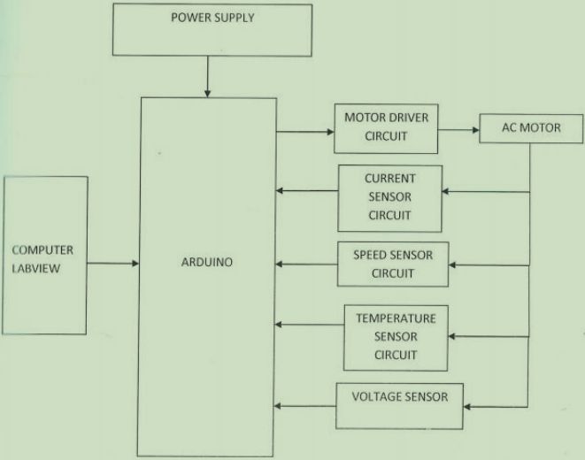
2.3.2 I then developed the schematic block diagram that showed complete project operation. I included power supply and computer LabVIEW along with the Arduino in the diagram. It included motor driver, speed sensor, voltage sensor, current sensor and temperature sensor circuit along with the AC motor all taking part in forming the complete schematic block diagram.
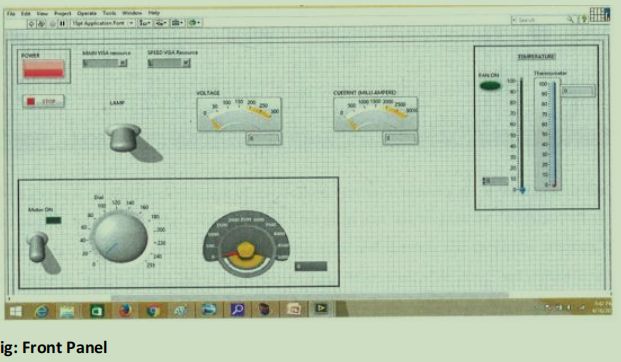
2.3.3 Then, I made the installation of the software for making communication between LabVIEW and Arduino. Implementation of software occurred in two parts one as a block diagram and another as a front panel. The front panel is for differentiating motor control section, measuring parameters, temperature control and system ON and OFF. The block diagram is a programmed part of LabVIEW and is the combination of symbols and various blocks.
2.3.4 I then carried out the implementation task of hardware. I implemented the systems hardware like motor, Arduino UNO, sensor module and a computer having LabVIEW software installed. I established computer communication through the use of visa recourse. I connected all the sensors to the Arduino.
2.3.5 I then carried out the designing of a circuit by the use of an appropriate transformer for measuring the single-phase induction motors voltages. I developed different circuits for the measurement of voltages required for different purposes such as for the industrial system to turn on, for controlling of the speed, for controlling of the amp and for the operation of the temperature sensor.
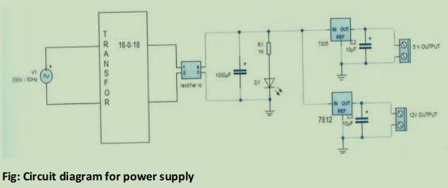
2.3.6 I then developed a circuit diagram showing the supply of the power for the entire circuit along with the detail presentation of the operation of the circuit. I finally prepared the hardware model consisting of all the equipment used in the project such as power supply board, sensors, Arduino and many other components.
2.4 TECHNICAL PROBLEMS AND SOLUTION
2.4.1 Problem in the coding of the LABVIEW program
During the installation of the software for making the connection of Arduino and LabVIEW program, I faced a problem of incorrect execution of the program. The problem created adverse effects on the command allocated to the system during the testing of the software installed and after the completion of the coding. I also found an error during the tasks performed by the command of G language. This created a problem in further proceeding of the project activities. The goal of the project in making the automation system cost-effective and timely completion got harmed as the delay in project activities also altered the scheduled time and budgeted cost. I then reviewed the entire coding procedure, along with the checking of the installed software. I also made the discussion with the project supervisor and with the team of experts in the field of coding and software installation. I also did some research using internet sources. After a long review and research, I found the coding used in the program had some issues which I eliminated after the thorough research. I then used the corrected coding and then translated them into the executable form of code for the execution by the program. I then merged both the source code and executable code and ran the program. This time the command executed well as per allocated and all the issues related to the G language also got eliminated.
2.4.2 Problem in using Arduino
During the testing of the system, I faced the problem of occurrence of the unstable board containing the Arduino or called a UNO board. This raised the problem of complete blockage of the work of automation system despite the successful connection of all the components.
Though I checked the connection of every components connection for ensuring no disconnected components available in the board. I also carried out the testing of the components attached to the UNO board such as adapter which could be AC and DC both, the USB connecting wire and many other supporting components making a complete UNO board. I tested if the power supply connection is proper but found no issues in the battery, i.e. powersupply. I then researched the problem using the internet and discussed it with the project supervisor. I made clear about the test carried out over the components of the Arduino UNO board which included ports for power in and out, DC power jack and USB power supply board along with the button for resetting. I then got suggested that the insufficient supply of voltage or voltage below 5 volts into the Arduino board may cause an unstable condition of the board. I then immediately checked the voltage, which was below 5 volts and immediately raised the supply of voltage above 5 volts. Then I found no such unstable nature of the UNO board. And hence I mitigated the unstable conditioned UNO board problem by raising the voltage up to sufficient limit and thus made the UNO board stable.
2.4.3 Problem with the speed sensor
During the testing of the speed sensor,I encountered a problem of negligible reflection of the IR light rays that are used for the detection of the speed of the motor which is one of the major tasks to be accomplished by the automation system. This created a problem in sensing the speed of the motor and also created a huge setback in the project activities. I then reviewed the components contributing to the formation of speed sensors such as diode emitting light and a diode detecting photo along with the rotating disc. But the test resulted positive. During the testing, I found a slight inclination of the rotating disc, which also contributes to reflecting the desired amount of IR light rays. I then adjusted the rotating disc, but the result came out to be the same. I then made the discussion with the seniors and mainly to the project advisor, and he suggested me that the surface texture of the rotating disc also plays an important role in reflecting a high amount of IR light rays. I then found rough and dark patches upon the reflecting surface of the rotating disc. I then glued a tiny white paper piece over the surface of the rotating disc and ran the test again. This time the sensor worked properly as the maximum amount of IR light rays got reflected on the photo detecting diode.
2.5 CREATIVE WORKS
I made the use of white paper over the surface of the rough rotating disc for covering the dark patches and made the successful working of the speed sensor. I also made the use of UNO board, which is one of the best Arduino board available in the market for the project.
2.6 TEAM COORDINATION AND PROJECT MANAGEMENT
I listed all the tasks to be performed in this project and allocated time for each task. A proper illustration of this process plan was done with the help of a Gantt chart. Being a solo project, I had to perform all the work which required effective time management. I hosted meetings with my supervisor and seniors for their suggestions on the issues faced during my work. I used my communication skill to gather the necessary information. A daily report was useful in keeping track of activities and for easier work management.
2.7 CODES AND STANDARDS
ISO 29.100.10, ISO 35.160 and ISO 31.040 were used for magnetic components, microprocessor system and resistors respectively.
2.8 SUMMARY
2.8.1 With this project, I was able to provide a system that assisted in industrial process management and cost control by using LabVIEW software. Successful monitoring and controlling of the system were done using this software. The implemented method could be used in different industrial applications and was suitable for maintaining the systems stability.
2.8.2 The project began with a proper literature review. I prepared a schematic block diagram highlighting major systems operation. Software implementation was done where various components were connected as required. Arduino and LABVIEW were the software used. It was followed by hardware components implementation where all the components were assembled and then tested.
2.8.3 This project dealt with creating an automated system in managing industrial processes for higher productivity and gain, which was precisely done with the use of LABVIEW. The obtained results were included in a report and were submitted to the department within the projects deadline.
Are you struggling to keep up with the demands of your academic journey? Don't worry, we've got your back! Exam Question Bank is your trusted partner in achieving academic excellence for all kind of technical and non-technical subjects.
Our comprehensive range of academic services is designed to cater to students at every level. Whether you're a high school student, a college undergraduate, or pursuing advanced studies, we have the expertise and resources to support you.
To connect with expert and ask your query click here Exam Question Bank
