7611ICT Computer Systems and Networks Report
- Subject Code :
7611ICT
- Country :
Australia
Overview:
Security systems are commonly used in home and business environments. These systems comprise of the physical hardware, such as sensors and alarms, software to determine responses to alarms, and contractual components, for example insurance and service plans.
In this assessment, you will develop a security system simulation as a Logisim circuit. The security system will have a pre-configured service plan and will require a user action when an alarm is triggered by a sensor (where the nature of the alarm and the sensor hardware are outside the scope of this assessment). The basic overview of the system is as follows.
The security system has a pre-configured service plan to determine what will happen if an alarm is detected. Service plan options include contacting a call centre, contacting a local security team, contacting the police or allowing the alarm to be cancelled.
When an alarm is triggered, the security manager must initiate an action from the following: Try call centre, Try security company, Try police, Try cancel. The minimum deliverable will require a Logisim circuit that tests the security managers action after an alarm notification against the pre-configured service plan. The assessment is split into Parts A (basic Logisim circuit), B (extended Logisim circuit) and C (report/interview) and each has deliverables and marking criteria. More details on all the assessment deliverables are below. And the submission instructions are on the last page.
Software requirement:
You must use the Logisim simulator Version 2.7.1 to create your circuits. Assignments submitted using other programs will NOT BE ABLE TO BE MARKED due to incompatible file formats.
Task Description: Logisim Part A and Part B
You are to build the following digital logic circuit in the Logisim simulator.
Labelling, neatness and wiring (5 marks):
Templates/Subcircuits (5 marks):
You must use templates (Logisim calls these subcircuits) to simplify the overall circuit design. Instructions for using templates/subcircuits are available on Learning @ Griffith in the Assessment 4 page where you downloaded this assignment.
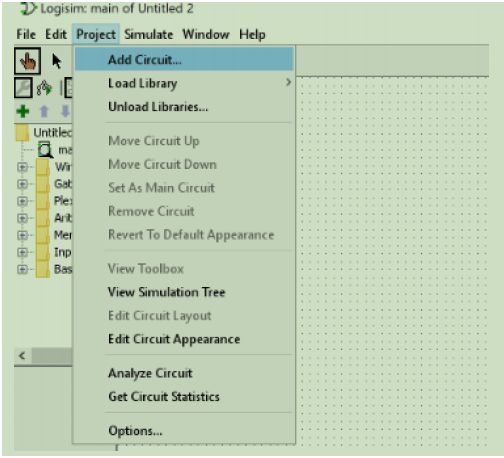
Note that when you create the template/subcircuit you must keep them within your single circuit file. Templates that are linked as separate files may not be able to be marked. To create a new template/subcircuit within your current file use the Project menu and the Add Circuit menu item only.
Requirements:
For this assignment you must implement the simulation of a simple home office security system. When an alarm occurs, the security system will take an action based on the system settings and check the level of insurance coverage to see if the requested action should be taken. There are 8 coverage levels represented by Input C, and four Actions represented by Input A. The system has 4 outputs, each of which represents one of the 4 possible actions.
The value of each output will be either 1 (action occurred) or 0 (action did not occur). A maximum of one of the four possible outputs will be active (1) for any given coverage and action combination. It is possible for no outputs to be active (all 0) if the Coverage and Action combination do not match the rules outlined below.
Coverage Input (C)
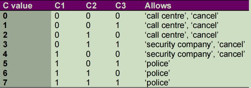
Input C represents the first input to the system and the level of coverage that the client has for the security system. Input C has values ranging from 0-7. The coverage level will determine what happens when an alarm is triggered and an action is requested. Coverage levels 0, 1, and 2 will allow a signal to the call centre. Coverage levels 3 and 4 will allow a call directly to the security company. Coverage levels 5, 6, and 7 will allow a call to the police. Coverage levels 0, 1, 2, 3, and 4 will allow the owner to cancel the alarm (calls to the police cannot be cancelled).
Action Input (A)
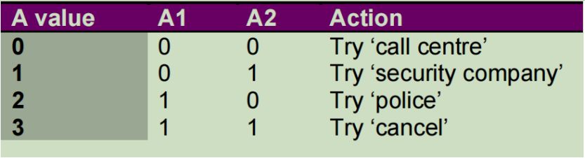
Input A represents the second input to the system and determines the action that is tried by the security manager when an alarm is triggered. Input A has values ranging from 0-3. Action 0 is to try to call the call centre. Action 1 is to try to call the security company. Action 2 is to try to call the police. Action 3 is to cancel the alarm.
Outputs (O1, O2, O3, O4)
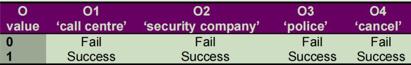
The four outputs (O1, O2, O3, and O4) are 1-bit outputs that are either 1 or 0 and represent what action has been taken based on the C and A inputs. If an output is 1 then the action is successful because the service coverage allows the action.
If an output is 0 then that action is not currently valid because the service coverage does not allow the action. A maximum of one output can be valid (i.e. 1) at a time. O1 corresponds to a call to the call centre. O2 correspond to a call to the security company. O3 corresponds to a call to the police. O4 corresponds to cancel.
Examples:
1. C=0, A=0: C=0 allows call to call centre. O1 is 1. O2, O3, O4 are 0.
2. C=0, A=2: C=0 does not allow call to the police. O1, O2, O3, O4 are 0.
3. C=1, A=0: C=1 allows call to call centre. O1 is 1. O2, O3, O4 are 0.
4. C=3, A=1: C=3 allows call to security company. O2 is 1. O1, O3, O4 are 0.
5. C=6, A=1: C=3 does not allow call to security company. O1, O2, O3, O4 are 0.
6. C=6, A=2: C=6 allows call to police. O3 is 1. O1, O2, O4 are 0.
7. C=4, A=2: C=4 does not allow call to police. O1, O2, O3, O4 are 0.
8. C=3, A=3: C=3 allows cancel alarm. O4 is 1. O1, O2, O3 are 0.
9. C=6, A=3: C=6 does not allow cancel alarm. O1, O2, O3, O4 are 0.
Note:
The examples on this page represent only some selected cases. There are more cases that result in. Your circuit must correctly show the correct outputs for each possible case.
Note: Your system can only use the allowed logic gates and components that are given in the problem description for Part A and Part B.
Representing C and A input values:
Input C will be represented by three inputs (3 bits). The three C inputs are named C1, C2, and C3. The table on the previous page shows the assignment of bits to each C value for C1, C2, and C3. Note the order of these bits. C1 is the Most Significant Bit (MSB) on the left.
Input A will be represented by two inputs (2 bits). The two A inputs are named A1 and A2. The table on the previous page shows the assignment of bits to each A value for A1 and A2. Note the order of these bits. A1 is the Most Significant Bit (MSB) on the left.
Part A (30 marks):
The implementation for this part must use only the three basic logic gates (AND, OR, NOT). Each AND gate and each OR gate can have only 2 inputs. More than 2 inputs for AND and OR gates is not permitted. Each NOT gate can have only 1 input. No other logic gates or circuits are permitted to be used in your circuit for Part A.
You are required to implement a circuit where the user (you) can input a number for Input C using value (C1, C2, and C3) and Input A using value (A1 and A2) and the circuit decodes the C1, C2, C3 and A1 and A2 values using a decoder (see lecture notes) made up of only the permitted logic gates. The output of the decoders is used to determine the outputs O1, O2, O3, and O4 based on the rules outlined in the requirements section above. Note that because of the decoding process you do not need and must not use an adder or other arithmetic circuit to calculate values.
The output of the circuit is via four output pins labelled O1, O2, O3, and O4. The output pin is the green circle in Logisim (shown below):
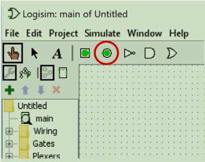
The four output pins must be labelled O1, O2, O3, and O4. An output pin is lit (1) only if the condition for the output is met as per the above requirements. A maximum of one output pin can be lit at a time. It is also possible that no output pins are lit based on the coverage and action inputs. Build your circuit so that it is as efficient as possible in terms of its use of logic gates and templates while meeting the requirements.
Template/Subcircuit requirement:
You are required to create a working and connected template/subcircuit for the following components:
Each decoder
The part of the circuit that determines the failure or success of the outcomes for C and A inputs
The whole of Part A for connecting into the Part B circuit
Testing
You will need to test various possible combinations for the inputs C1, C2, C3, A1, A2 and check if the desired output is obtained for Part A. You do not need to submit your tests.
Part B (20 marks):
For this part, the simulation will count how many alarm service requests have been triggered in Part A. You must use the same circuit that you built in Part A and extend it for Part B. In Part B you will be counting the various types of service requests and determining whether to stop the simulation based on the requirements below.
Requirements:
The security service counts call centre, security company, and police alarms separately. This means that there are separate counts for call centre, security company and police alarm requests. A cancel alarm signal will reset the count for the call centre and security company alarms to 0. It will not affect the count for the police alarms.
The security service has a limit of E call centre alarms, F security company alarms, and G police alarms for the duration of the plan. E, F and G are 3-bit inputs with values that range from 0 to 7. The values for E, F, and G are chosen and input manually once by the user of the simulation and must stay the same for the duration of the simulation. The values for E, F, and G can change for each simulation.
If E call centre alarms or F security company alarms are made (and no cancel signals arrive to reset the alarm count), the service is shut off and an output pin labelled System Inactive is set to 1. At this point the simulation must stop and no changes to the System Inactive output of the circuit will be permitted after this happens. If G police alarms are made the service is shut off and an output pin labelled System Inactive is set to 1. At this point the simulation must stop and no changes to the System Inactive output of the circuit will be permitted after this happens.
Being in the System Inactive state still allows changes to the C and A values using their inputs and send call centre, security company, police and cancel signals, but these must not affect the System Inactive output of the Part B circuit which should remain set to 1.
Build your circuit so that it is as efficient as possible in terms of its use of logic gates and templates while meeting the requirements.
Part B Implementation Requirements
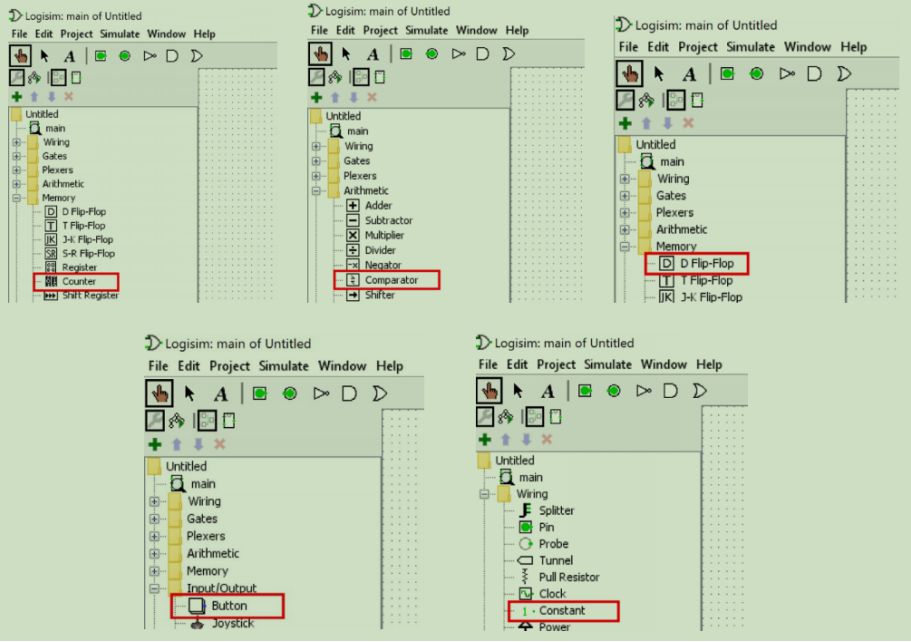
For Part B you may use only the following (you may use more than one of each):
The three basic logic gates
(AND, OR, NOT). Each AND gate and each OR gate can have only 2 inputs. More than 2 inputs for AND and OR gates is not permitted. Each NOT gate can have only 1 input.
The counter (3 bit, no wrap around) circuit from the Logisim circuit library. .
The comparator (3 bit, unsigned) circuit from the Logisim circuit library. .
The D FLIP-FLOP circuit from the Logisim circuit library. The prebuilt D FLIP-FLOP circuit can be used to remember some information. .
Buttons and Constants..
Note:
For Part B you will need to add a button that is pressed by you after the C and A inputs have been entered. This is to avoid counting while you are adjusting the input pins for the C and A input pins (C1, C2, C3, A1 and A2)..
Template/Subcircuit requirement:
For Part B you do not need additional templates.
Testing
You will need to test the circuit to confirm that it functions correctly as per the requirements. You do not need to submit your tests.
Interview (30 marks):
You will be asked to clearly demonstrate your understanding of your circuit and of its operation to your workshop demonstrator.
Interview requirement: Online students
In the interview you will be required to share your screen, turn on your camera, and use a microphone to communicate with your workshop demonstrator. You will also be required to complete a booking for the interview during weeks 11 and 12. More information will be made available about the process closer to week 11.
Interview requirement: On-campus students
You will complete an in-person interview during either your normal week 11 or 12 workshop time. More information will be made available about the process closer to week 11.
Report (10 marks):
Your report 2 pages maximum must contain the following sections:
1. Your details: Name and student number
2. Screenshots of your circuit diagrams:
1. A screenshot of your whole circuit including both Part A and Part B. This screenshot the overall circuit and may also show subcircuits/templates. If you have not completed Part B then only submit what you have completed.
2. A screenshot of your Part A circuit that shows the decoder and the C and A combination logic sections. This screenshot may include subcircuits/templates.
3. A screenshot of the inner circuitry of one of your decoders. The inner circuitry refers to the actual logic gates and not the subcircuit/template drawing.
4. A screenshot of the inner circuitry of your C and A combination logic. The inner circuitry refers to the actual logic gates and not the subcircuit/template drawing.
If you have broken your C and A combination logic up into smaller subcircuits show the inner circuitry for these also.
Circuit Function:
A brief (maximum 300 word) description of your circuit describing concisely and correctly in your own words how the circuit operates.
