MEC2402 Stress Analysis Assignment
- Subject Code :
MEC2402
- Country :
Australia
Question 1: Beam Bending Experiment (120 marks)
Overview
For your response to this question, you must develop your own bending experiment using a four-point bending configuration. You must thoroughly document and analyse the experiment including a detailed analysis of the stress and deflections associated with the loading on the beam. To simplify the analysis in Question 1, you should consider a beam that has a symmetric cross section. (In Question 2 you will treat the more complicated case of asymmetric bending.)
Safety elastic energy storage in a beam
If the mass used to load the beam is and gravitational acceleration is and the vertical deflection of the beam at the point of loading is ?, then conservation of energy principles dictate that the elastic energy stored in the beam will be given by E=1/2mgh
In the case where an experimental configuration uses the specified maximum values of kg and ? = 100 mm, and is taken as ? 9.8 m/s2 , the maximum allowable stored elastic energy is around 0.5 Joule. This is a relatively small quantity of energy, but it might still represent some danger if that energy was somehow focussed into a light-weight, sharp-edged object that accelerated and hit someones eye of another part of their body.
Another source of danger, that is perhaps more significance and that should be considered is the loading mass that might fall from the beam. A mass of 1 kg falling through a distance of perhaps 1 m to the floor will impact with an energy of 10 Joule, and if such an impact was absorbed by your big toe or some other part of your body, a significant injury may be sustained.
Operating Limits & Safety Risk Management
The arrangement of your bending experiment should be such that easily measurable deflections (of at least several millimetres but no more than 100 mm) can be achieved for relatively low loads (of no more than 1 kg in mass), and your beam should be of a ductile metallic material.
These operating limits have been specified based on my (David Buttsworths) assessment of risks associated with you independently designing and performing a successful experiment at home. The task of managing health and safety risks is frequently considered to be a four-step process. For example, see: https://www.worksafe.qld.gov.au/safety-and-prevention/creating-safe-work/managing-risks
Tasks
- The requirements for modest loading and a ductile beam material are imposed so that it is unlikely the stored elastic energy in the beam will cause injury in the case of sudden load slippage or failure of the support structures, or rupture of the beam. Under these conditions, the potential for injury or property damage should be low, however, you must still take care in establishing and using your experimental configuration. Discuss, using illustrations as appropriate, the hazards associated with establishing and performing your experiment. That is, describe the things that might go wrong, and describe the types of injury or property damage that might occur if something does go wrong. Also describe the strategies you have adopted to ensure that risk of injury or property damage is essentially eliminated. Present a photograph of the experimental apparatus that you have personally developed and include your student photo-ID clearly in your response to this part to demonstrate that you, the person enrolled in MEC2402, are personally providing the requested responses in this assignment. Note that while your response to this part of the question draws the maximum awarded marks as indicated, designing and performing an appropriately safe experiment is a critical part of this assignment. It is essential that you complete this part of the question satisfactorily. The remainder of the assignment will only be marked if you present an adequate response in this task. [20 marks]
- Produce a simplified sketch of the beam arrangement with appropriate dimensions that illustrate the magnitude, position and direction of the load and the support reactions. Describe the methods and assumptions that you are using to define sizes and distances plus the magnitude of the load (the applied force) and any assumptions that have been made in defining these quantities. Describe the degree to which your beam support(s) approximate the idealised simply-supported arrangement. [10 marks]
- Produce a sketch of the cross section of the beam that defines its overall geometry and dimensions, including section thicknesses as appropriate. Describe the methods you have used to define the section geometry, including discussion of assumptions/analysis; identify if your beam is a standard section, or if it is produced as a bespoke section. Present your calculations of the principal second moments of area for the section, and describe the methods that you have used to verify the accuracy of your calculations. Note that even if your beam has a standard section for which you can look up section properties, you can use these section properties as a cross-reference, but you are still required to present your own working and calculations. [10 marks]
- Identify the location, magnitude and direction of the maximum bending moment within the beam. [10 marks]
- Calculate the maximum tensile and compressive stresses due to the bending moment within the beam and show the location where these stresses occur relative to the neutral axis on an appropriately labelled sketch of the section. [20 marks]
- Identify the beam material, its strength and elastic properties, describing and justifying assumptions as required. [10 marks]
- Take two photographs of your beam with an appropriate scale within the field of view.
- The first picture should be of the beam without any load and should provide the undeformed (unloaded) shape of the beam.
- The second picture should show the deflected shape of the beam when loaded. Analyse your photograph(s) to determine the maximum deflection of the beam for the given load. Compare your result to theoretical results and discuss whether your results are reasonable or whether certain modelling/analysis improvements need to be made. [25 marks]
- Present your own solution to two (2) of the even-numbered tutorial problems that are relevant to the analysis you have presented in answering the earlier parts of this question. Describe how the completing these tutorial problems is relevant or is related to the earlier parts of this question. [15 marks]
Question 2: Asymmetric beam section (80 marks)
For this question, you are going to develop and analyse an asymmetric beam section generated by combining three sections considered in Question 1 into a single composite section that does not have any axis of symmetry.
In contrast to Question 1, it is acknowledged that this task is motivated by theory rather than practice. (I cannot readily conceive of a reason that an engineer might be asked to design a strongly asymmetric section per se.) However, asymmetric beam sections are used for practical reasons in different applications. By attempting this question, you have the opportunity to demonstrate your knowledge of bending of asymmetric beam sections.
- Design your asymmetric section and complete the required tasks as described below.
- First join two identical sections from Question 1 together they must contact each other at one or more points such that the combined section has one or more planes of symmetry, and the ratio, Imax/Imin is minimised for this two-section combination.
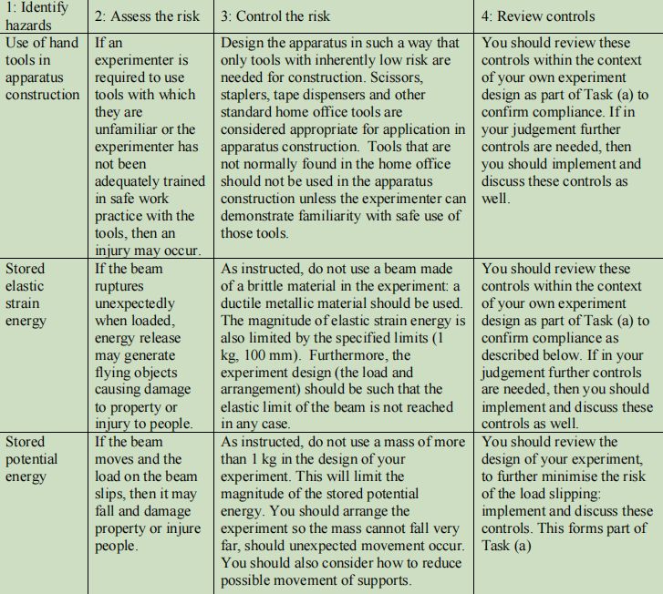
- Now join the third section from Question 1 onto the section formed in (i) in a manner that achieves a specified asymmetry of the combined section. The added third section must contact the other combined section at one or more points. In the present context, the specified asymmetry requires the new section to not have any planes of symmetry, and the principal centroid axes (PCAs) for the asymmetric section will be separated from a plane of symmetry of section (i) the by the target value of 32.5 degrees. To illustrate the requirements in this part of the question, suppose the section used in Question 1 looks like this:
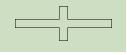 To complete element (i) above, we might consider joining two sections together to create a combined section like this:
 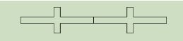 However, while this combined section actually has two planes of symmetry, it does not satisfy the requirement that the ratio Imin/Imax is minimised. Lets proceed by assuming that the dimensions are such that Imin/Imax is minimised with this configuration:
  Now, to tackle task (ii), we need to consider arrangements for joining the third section such that the angle of the PCAs is separated by 32.5 degrees from the plane(s) of symmetry in part (i). Such a requirement might be satisfied with an arrangement such as:
 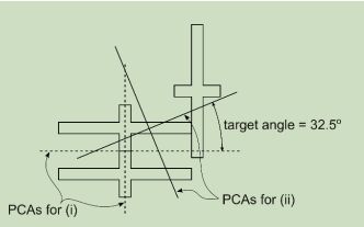 Explain the rationale for your arrangement, including sketches and completing calculations to demonstrate how the beam section you have developed satisfies the requirements as described above. Through your calculations, you must also define the centroid location and the orientation of the principal centroidal axes and the magnitudes of the associated second moments of area. Show these axes and their orientation on a sketch of the section and indicate which of the two axes corresponds to the Imax axis. [50 marks]
- If a bending moment in the orientation identified in Question 1 (part d) is applied to the asymmetric section being considered in the present question, identify the orientation of the neutral axis and show this orientation on a sketch of the section. [10 marks]
- For the loading considered in part (b), identify the location on this asymmetric section where the tensile and compressive stresses will be largest in magnitude, calculate what these values are, and show the locations of these values on a sketch of the section. [10 marks]
- Present your own solution to one of the even-numbered tutorial problems that is relevant to the analysis you have presented in answering parts (b), (c) and (d) of this question.Describe how completing this tutorial question gives you confidence that your responses to parts (b), (c) and (d) are correct. [10 marks]
Question 3: Shear in Beams (50 marks)
Re-consider the original (symmetric) beam configuration that you have analysed in Question 1 and complete the following tasks.
- Using a labelled sketch of the beam showing the loading, reactions, and key dimensions, identify the location and magnitude of the maximum shear force acting on the beam. [10 marks]
- For the shear force and its location as identified in part (a), calculate the shear stress at 4 locations (other than free surfaces) within the section, including the location where you think shearing stresses are going to be highest. [20 marks]
- Produce a sketch of the beam section illustrating the variation and direction of shear stresses across the beam section. [20 marks]
Question 4: Elasto-plastic Analysis (70 marks)
Re-consider the original (symmetric) beam configuration that you have analysed in Question 1 and complete the following tasks, supposing that the beam is made of a perfectly elasto-plastic material with a yield strength equal to the value specified in Question 1(f).
- Under the conditions defined above, what is the maximum elastic moment for the section? [10 marks]
- Identify the plastic moment and the shape factor for the section. [10 marks]
- Produce a sketch showing the distribution of stresses across the beam section for an applied moment of M = (3/4My+1/3Mp)[20 marks]
- (d) Produce a sketch showing the distribution of residual stress across the beam section if the moment applied in part (c) is removed. [20 marks]
- Present your own solution to one of the even-numbered tutorial problems that is relevant to your answers in this question. Describe how it is relevant. [10 marks]
Question 5: Buckling Analysis (30 marks)
Re-consider the original (symmetric) beam configuration that you have analysed in Question 1 and complete the following tasks, supposing that the beam is not carrying any bending loads but is instead only carrying a compressive load acting through the centroid of the section. Under these conditions, the beam can be treated as a column, and some form of buckling analysis should be performed. For the analysis in this question, adopt the same material properties you have already identified for the beam in Question 1.
- Based on the configuration considered in Question 1, define the effective length of the column that you are going to adopt for the analysis. [5 marks]
- Calculate the Euler critical buckling load for this configuration and identify the direction in which the column would bow-out if buckling occurs. [20 marks]
- If buckling is prevented from occurring, what compressive load would be required to generate yield in the column, and therefore would you say this column is long or short? [5 marks]
