Pump Jack Engineering Drawing Assessment
- Country :
Australia
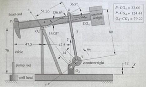
Figure 2. Pump jack for the project (all linear dimensions are in inches).
Requirements:
- For the position shown, draw free-body diagram of the crank (2), connecting rod (3), and walking beam (4) including the weight acting at the CG of the walking beam and the crank but not the connecting rod.
- Determine the pin forces on the walking beam, connecting rod, and crank and the reaction torque on the crank based on the data in the table. (Hint: you can assume that the crank turns slowly enough that accelerations can be ignored.)
