Road Design-Surveying Exercise
- Country :
Australia
Using the plan provided, and meeting the criteria set out below, you must make a preliminary design for a private road to access a rural property. The three straights of the road have been shown on the plan. The road starts at Ch 00 on Tuckers Lane.
1, USING THE PLAN PROVIDED TO FIX THE STRAIGHTS (9 MARKS)
The plan was originally drawn at a scale of 1:2,000 but after scanning and printing it may not now be at that scale.
You must find the scale of your plan.
As well as the bar scale showing 100m, there are three surveyed lines, for which precise horizontal distances are known and are shown on the next page. Measure each of the four lines in mm and show these measurements in your answer sheet. Using the given (true horizontal) distances, compute the scale of your plan and state this in the answer sheet.
(4 Marks)
The plan provided has a contour interval of 5m. Assume that the contours are correct with 90% confidence.
Using your plan, by scale, find the bearings and distances of each of the three straights.
Quote your answers to the nearest metre and nearest degree and adopt these values as being fixed for each straight. (i.e. each straight will be exactly an even metre long and have a bearing precise to one degree only.) Use Tuckers Lane as your azimuth. (3 Marks)
Mark the bearing and distance of each straight on your plan. This must be attached to your answer. (2 Marks)
2. CHAINAGES FOR THE HORIZONTAL ALIGMENT OF THE ROAD (18 MARKS)
Determine the deflection angle at each I.P. (4 Marks)
Each horizontal curve is to have radius of 44m.
Calculate the tangent distance and arc length for each curve (to 2 decimal places) and show them in the table of answers. (4 Marks)
Calculate the changes of each of the four horizontal curve T.P.s and the end of the road, and any other points listed, and show them all in the table of answers. (10 Marks)
You will need to use these values in the rest of your design; e.g. for the end of the road and the TPs.
On your plan, plot each TP, and then draw in the horizontal curve. (Calculating the external distance will give you a third point to help you draw the curve freehand.) Also clearly show the lengths of each straight (IP - IP) and the bearing of that straight.
3. VERTICAL ALIGNMENT (23 MARKS)
Using the information shown on your contour map, draw a long section of the Centre Line of your road at scales; horizontal 1:2,000 and vertical 1:200. (Please read the submission section for detailed guidance about drawing the long section.) Scale the distances along the road to each contour and show the results on the table of your answer sheet. (5 Marks)
Design a vertical alignment of the centre line of the road showing grades and vertical curves. The vertical alignment must meet the following criteria: The road must start at RL 23.0. It must finish exactly at RL 18.2, at the change you have calculated as being the end of the road.
The Natural Surface RLs at the start and end of the road are exactly the same as the starting and finishing Design RLs of the road at each point.The first IP of the vertical design must lie at Chainage 120 and RL 14.48. After that you must complete the vertical design using two (2) (or three at most) rising grades and one falling grade, which generally follow the land surface. You must aim to keep the road (i.e. the cut or fill) within 1.0m of the natural surface. If this cannot be achieved in a maximum of four new grades, complete your design using four grades and then make a brief report and explain where the road has excess cut or fill and by how much.
The maximum grade allowed at any point along the road is 10%.
Vertical curves must have lengths of only 60m, 80m or 100m. The I.P. of each vertical curve must be located at an even 10m chainage (i.e. 120, 350 etc. and must not be placed at odd locations such as 376.5). All grades used must be to no greater precision than 0.1%, except for the final grade to the end of the line. (i.e. grades such as 3.1% must be used for every grade, except the final one where additional decimal places may be shown, if necessary, to ensure that the Design RL meets the set RL.
Every change of grade requires a vertical curve. (Assume that your road will meet Tuckers Road precisely at the nominated RL. No vertical curve will be needed at this road junction.)
Complete the table with your vertical curve calculations for the design levels.
Calculate the Design Levels at every 10m of running chainage along the road. Also calculate the chainage (to 2 d.p.) and RL of the low point of the road at the river crossing. River and River Crossing Information The banks of the river where the road crosses it are at R.L. 14.0
At the river crossing, the design level of the road must be between 1m and 1.5m above the riverbanks to allow for a culvert to be built. If you believe that this cant be achieved design the road to be as close as possible to this specification and report the difference.
4) TRAVERSE CALCULATIONS TO SET OUT THE END OF THE ROAD (10 MARKS)
A survey party has run an accurate EDM traverse from point X via Y to A, and then connected to the start of the road (Ch 00).
The coordinates of A are 600.000m E, 400.000m N.
Both A and Ch 00 lie on the Centre Line of Tuckers Lane.
The bearings and distances are:
| Theodolite and EDM set up at Y | |
|---|---|
| Horizontal Angle X-Y-A | 151o 31 20 |
| Horizontal Distance Y X | 81.645 |
| Theodolite and EDM set up at A | |
|---|---|
| Horizontal Angle Y-A-Ch00 | 87o 04 25 |
| Horizontal Distance A Y | 315.740 |
| Horizontal Distance A - Ch00 | 180.350 |
Calculate the coordinates of point X using the survey data above. Also, using your bearings and distances of each straight of your road, calculate the coordinates of the end of the road. Then, using the coordinates calculated for X and the end of the road, calculate the bearing and distance for a survey party to set out the end of your road from point X.
While not needed in your submission, you may find it helpful to note the angles, bearings and distances of the traverse on your plan.
5) HORIZONTAL CURVE SET OUT DATA (8 MARKS)
Please calculate the data needed to set out each horizontal curve from its first T.P. by deflection angles and long chords. The points to be set out are: running changes of every 10m along the road (i.e., 120, 130 etc), the Crown of the curve and the second T.P.
6) SURVEY PARTY INSTRUCTIONS (6 MARKS)
There is a survey party at your disposal. They now have the data to set out the end of the road from Point X and the horizontal curves. They made a start on a more detailed survey, as shown below, which allows you to calculate an estimate of some volumes of cut or fill required.
Please provide instructions to the survey party for them to gather any more information needed or areas to be checked so that you can finalise your road design.
7) VOLUME ESTIMATION (6 MARKS)
The survey party has started to do a detailed set out of the road and has levelled every 10m from change 10 to change 70 along the road centre line with the results shown below.
DO NOT USE THESE RLs FOR YOUR LONGSECTION. THEY ARE FOR THIS CALCULATION ONLY.
| Chainage | 10 | 20 | 30 | 40 | 50 | 60 | 70 |
| Nat Surf RL | 21.98 | 21.15 | 20.20 | 19.36 | 18.82 | 17.95 | 17.35 |
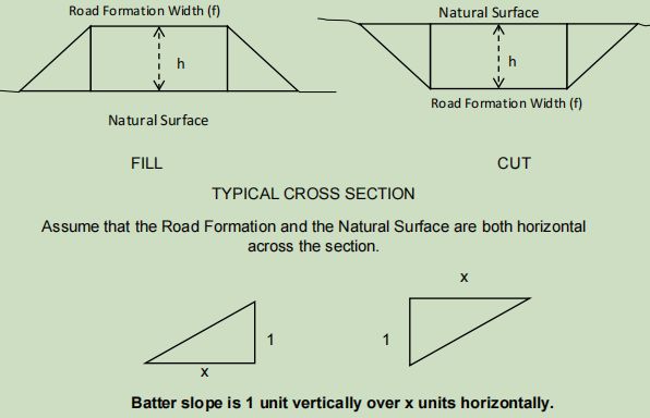
The width (f) of the road is 4.8 m and the batter slope (x) is to be 1 in 2.3. (See the diagram below.)
Using your design levels for your road, the RLs above, find h at each 10m location. Use the typical Cross Section shown below, to calculate, using the End Area Formula, how much cut or fill will be needed between chainage 10 and change 70.
TYPICAL CROSS SECTIONS
GENERAL COMMENTS
All Changes for horizontal T.P.s etc should be quoted to two decimal places. For the horizontal curve setting out data, please show the arc lengths and long chord distances to two decimal places of a metre and the setting out deflection angles to the nearest 1.
All levels on the long section table must be correct to two decimal places. The grades you nominate for the road design must be to no greater precision than one decimal place, except for the final grade, and all R.L.s must agree perfectly with the grade shown. Your road must end exactly at R.L. given at your calculated change for the end of the road.
Sometimes an Engineer is asked to attempt a design which cannot meet the clients specifications. If you believe this has happened, do a design which comes as close as possible to the specifications and report the problem areas at the end of your answer sheet.
This exercise is an assessment of the work done in the Surveying subject this semester. Do not research road design information and go beyond the calculations shown to you in the Surveying classes. You will be marked on the accuracy of your calculations and meeting the specifications.
