Topological Map Generation Using Hardware Robot ENG4701 Project
- Subject Code :
ENG4701
- University :
Monash University Exam Question Bank is not sponsored or endorsed by this college or university.
- Country :
Malaysia
Topological Map Generation Using Hardware Robot
ENG4701 Project Proposal
Author: Trisha Lim Ruo Jing (32797389)
Supervisor: Dr.Patrick Ho
Project type: Research
1. Introduction
In the realm of robotics and autonomous navigation, the creation of accurate and efficient maps remains a crucial challenge. While significant advancements have been made in Simultaneous Localization and Mapping (SLAM) techniques, generating topological maps that capture the higher-level relationships between spaces and landmarks remains an ongoing area of research.
Topological maps offer a unique perspective on the environment, emphasizing the connectivity and relationships between spaces rather than precise geometric details. Unlike traditional maps that focus on precise distances and directions, a topological map prioritizes the relationships between places and features. It strips away unnecessary details, leaving a simplified representation that highlights the connectivity between points. These maps are invaluable for tasks such as navigation, path planning, and scene understanding.
While several algorithms exist for topological map generation, their implementation often relies on simulated environments or post-processed sensor data. However, translating these theoretical advancements into real-world applications presents unique challenges, including sensor noise, dynamic obstacles, and varying lighting conditions. This project aims to bridge the gap between theory and practice by deploying a physical robot to generate topological maps in real-world scenarios.
The motivation behind this project stems from the topological map generation algorithm done by previous final year students, offering a valuable abstraction of the environment. To complete and prove the feasibility of the topological map generation algorithm, this project will involve the development of a robot equipped with essential sensors, the integration of the topological mapping algorithm, and the validation of its performance in various test environments. This proposal outlines the research, design, and implementation steps, addressing potential risks and management strategies to ensure successful project completion. The project will focus on implementing the existing algorithm through real-world experimentation, taking into account the unique challenges posed by sensor noise and dynamic environments. The outcomes of this project will contribute to advancing the field of robotics, ultimately leading to more robust and reliable topological mapping solutions.
2. Aims and Objectives
2.1 Aims
To design, develop, and evaluate a hardware robot capable of autonomously generating and navigating topological maps of real-world environments derived from conventional maps, demonstrating the practical application of the topological mapping algorithm to enhance the efficiency and accuracy of robotic navigation.
2.2 Objectives
- To design and construct a mechanical robot capable of navigating according to the topological map generated by the software algorithm, equipped with Lidar, IMU and wheel encoders to provide data for mapping and localization.
- To adapt and integrate an existing topological map generation algorithm to process the sensor data and leverage computational capabilities of the robot for real-time performance to generate a map of the robot's actual path.
- To compare the actual path map generated by the robot with the fed-in topological map generated by the existing algorithm, and evaluate the accuracy using metrics like map overlap.
3. Literature Review
3.1 Introduction
In recent years, the field of robotics has seen significant advancements, particularly in autonomous navigation and mapping. One of the critical challenges in this domain is enabling robots to navigate complex environments efficiently and accurately. [1] Traditional methods, such as metric mapping, often struggle with scalability and adaptability, especially in dynamic or large-scale environments. To address these challenges, researchers have increasingly turned to topological mapping as a viable alternative. [2] Topological maps abstract the environment into a graph of nodes and edges, representing significant places and the paths connecting them. [3] This abstraction simplifies the navigation problem and enhances the robot's ability to operate in diverse settings.
This literature review aims to provide a comprehensive overview of the current state of topological mapping and its application in robotic navigation. It begins by exploring the foundational concepts and various algorithms used in topological mapping. Subsequently, it delves into the sensory technologies that enable accurate perception and environment mapping. The review then examines the design and architectural considerations for building a robot capable of implementing these algorithms. Additionally, it addresses the software integration challenges and real-time processing requirements essential for effective navigation. The review concludes with a discussion on testing methodologies and the potential challenges and limitations encountered in deploying such systems.
3.2 Overview of Robot Navigation
Effective robot navigation is essential for enabling robots to move autonomously and interact with their environment safely. To achieve this, robots need to master several key components of navigation, which are covered in this section. These components include localisation and positioning, real-time data processing and path adjustment, and obstacle avoidance in dynamic situations. [8] Gaining an understanding of these elements is essential to create reliable autonomous systems that can navigate complex interior environments.
3.2.1 Localisation and Positioning of Robot
One of the main challenges in indoor robot navigation is determining the precise location of the robot. Unlike outdoor situations, where GPS devices offer dependable positioning data, indoor surroundings do not offer such simple answers. This limitation brings in the need of sophisticated sensor fusion methods and visual perception capabilities. [4] High-level sensor fusion is a technique used to track the position of the robot in the environment and generate precise maps using data from several sources, such as light detection and ranging (LiDAR), cameras, and inertial measurement units (IMU). [5] Visual perception further enhances this process by enabling the robot to recognise features and landmarks, aiding in more accurate localisation. In addition to that, the method of odometry calculation uses data from the encoders of the DC motor and the IMU of the robot to estimate its position over time. While odometry can provide useful information, it may accumulate errors, which is why it is often combined with other methods to improve accuracy. [4]
3.2.2 Real Time Data Processing and Path Adjustment
Building on accurate localisation, navigating in an ever-changing environment requires a robot that continuously fine-tunes its path based on the real-time environment. Figuring out a collision-free route that also keeps the journey as efficient as possible is quite a challenging task. For the robot to move safely, it needs to process data instantly and react promptly to any new obstacles and changes. This need for real-time data processing and path adjustment poses significant computational challenges, as the robot must balance the demands of fast processing with the accuracy of its navigation decisions. Simultaneous localisation and mapping (SLAM) comes in handy in this case. [7] This technique is used to create a map of an unknown environment while simultaneously keeping track of the robots location within it. [5][6] Crafting effective solutions means creating smart algorithms and using powerful computing resources to ensure the robot can navigate swiftly and accurately in real-time.
3.2.3 Obstacles Avoidance in Dynamic Environments
Beyond just knowing the robots location and adjusting its path, indoor spaces are often chaotic and dynamic, with moving obstacles like people, making navigation and obstacle avoidance a tough job for autonomous robots. Traditional obstacle detection methods in indoor environments face significant challenges. For example, the difficulty of representing obstacles at varying heights with 2D laser rangefinders, ineffective detection and navigation around dynamic obstacles, and issues with complex shapes that LRFs struggle to reliably detect. To overcome these problems, the robot needs advanced path planning and obstacle avoidance algorithms by integrating multiple sensors and advanced algorithms to manoeuvre through such complex environments. [9] Proposed solutions include data fusion of depth cameras with LRFs to enhance obstacle awareness, and applying path optimisation techniques to shorten trip times and boost navigation effectiveness. [10] These enhancements have been validated through simulations and real-world experiments, significantly improving the safety, and reliability of mobile robot navigation indoors.
3.3 Robot Sensing Technologies
To enable all these navigation capabilities mentioned above, various sensing technologies are utilised to enhance robot navigation abilities. By leveraging these sensors, robots can accurately perceive and interact with their environment, overcoming the inherent challenges of indoor navigation. Some common sensing technologies discussed include 2D Lidar, IMUs, encoders and laser range finders, each contributing uniquely to the overall navigation strategy. [11][12] 2D Lidar provides high-resolution distance measuring to surrounding objects by bouncing light off a single surface. To enable a more precise mapping and localisation, 3D Lidar that advances 2D Lidar by using multiple beams of light simultaneously to create a three-dimensional view is coming in handy. [13][17]
To measure the robots orientation and acceleration, inertia measurement units are used in a robot. [11] IMUs typically consist of accelerometers and gyroscopes, with some incorporating magnetometers. With these components in the IMUs, linear acceleration, angular velocity, and strength and direction of the magnetic field of the robot can be measured. [14] The data from these individual sensors is often combined using techniques like Kalman filtering to provide a more accurate and complete picture of the device's motion and orientation. [14][15] IMUs do not rely on external signals like GPS which make them suitable for indoor environments. They can also read and provide data at high frequencies, enabling the capture of rapid movements and changes in orientation. [15] Motor encoders can be used to measure the robots wheel rotations. This data, combined with IMU readings, is used for odometry-based motion estimation, allowing the robot to track its position and movement accurately. [11]
3.4 Overview of Robot Operating System (ROS)
Having explored the sensing technologies that provide the raw data for robot navigation, the attention is now turned to the software framework that orchestrates these diverse components - the Robot Operating System (ROS).
3.4.1 ROS Framework Overview
The ROS framework stands for a widely adopted, open-source framework that provides a flexible and modular architecture that allows developers to create complex robotic systems. It offers a collection of tools, libraries, and conventions that simplify the task of building and programming robots. The framework supports various programming languages, primarily Python and C++, enabling developers to choose the most suitable language for their applications. The modularity of ROS allows for the integration of different components and breaking down functionalities into reusable packages, promoting code reusability and making it easier to manage and update individual parts of the robot's system. The framework's communication mechanisms, such as topics and services, enable seamless data exchange and interaction between different components of the robot system. While ROS presents many advantages, it is important to also consider its limitations. It can be demanding on system resources, which may limit its use in low-power devices.
3.4.2 ROS-Enabled Hardware Integration
One of the key strengths of ROS lies in its ability to facilitate hardware integration. ROS excels in facilitating the integration of various hardware components, such as sensors, actuators and controllers, through standardized interfaces. This integration allows for seamless communication between hardware and software, enabling real-time data processing and control. [18] However, the integration can sometimes be challenging due to the diversity of hardware and the need for compatible drivers. To overcome these limitations, the ROS community actively develops and maintains a comprehensive set of hardware interfaces and drivers, ensuring that new devices can be quickly supported. Local processing is also implemented to reduce latency and improve response time.
3.4.3 ROS-Powered Software Architecture
Beyond hardware integration, ROS also provides a robust software architecture that underpins the entire robotic system. The software architecture of ROS is designed to support distributed computing, allowing multiple nodes to communicate over a network on different machines. [19][20] This architecture enables the separation of concerns, where different nodes can handle specific tasks such as perception, planning, and control. If one node fails, the other can continue to operate, ensuring the systems robustness. Despite these advantages, distributed computing also comes with its own set of challenges. Managing communication between nodes can introduce latency and complexity. To address these issues, ROS provides tools for monitoring and debugging node interactions, as well as optimizing data flow through techniques like message filtering and compression.
3.4.4 ROS-Based Simulation and Visualization
In addition to its real-world capabilities, ROS also offers powerful simulation tools such as Gazebo, which is used to test and visualize the robots in a virtual environment before deploying them in the real world. [18] This capability is crucial for validating algorithms and ensuring safety. This capability significantly reduces the risk of hardware damage and accelerates the development process. However, it is important to acknowledge that simulations are not a perfect replica of reality. Discrepancies between simulated and real-world performance can lead to challenges when transitioning from simulation to actual deployment. To mitigate this, the developers are encouraged to use realistic models and scenarios in simulations and to iteratively test and refine the systems in a real-time environment.
3.5 Conclusion
In summary, this literature review underscores the necessity of addressing the challenges inherent in real-world topological map generation for autonomous robots. Traditional mapping techniques often break down in dynamic and large-scale environments, prompting the exploration of topological mapping as a robust alternative. Through the examination of various algorithms, sensor technologies and the pivotal role of ROS, this study delves into the complexities of enabling robots to perceive, understand, and navigate their surroundings effectively. One important tool that appears is the Robot Operating System (ROS), which allows for software modularity, hardware integration, and simulation capabilities. While problems like sensor constraints and real-time performance still exist, there are encouraging ways to get around them with the help of strategies like sensor fusion, adaptive algorithms, and thoughtful system design. By adopting and refining the topological mapping algorithm proposed by Chew Jing Wei, alongside leveraging the power of ROS, this project aims to contribute to the advancement of autonomous robot navigation based on topological maps in real-world scenarios.
4.Methodology and Methods
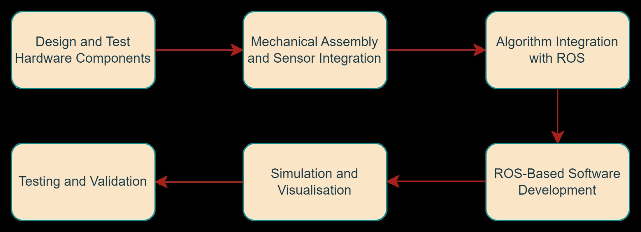
Figure 1. Workflow of constructing hardware robot
As illustrated in Figure 1, there are few proposed methods for constructing a hardware robot:
- Robot hardware design, construction and sensor integration
- Algorithm integration
- ROS implementation
- Simulate and visualize the performance of robot
- Test and validate the robot performance with the existing topological map
4.1 Robot Design and Construction
4.1.1 Mechanical Design
The mechanical design of the robot aimed to create a stable and efficient platform optimized for navigating a hard and smooth indoor environment. The design has to prioritise balance, durability and maneuverability. The robot features a double-decker chassis, with the lower-level housing the battery, Raspberry Pi, DC motor and motor driver, while the upper level is dedicated to mounting the Lidar and IMU sensors. The chassis of the robot will be designed to be lightweight yet strong enough to support all components on it, using materials such as acrylic. [16] The layout will ensure all components including all batteries, motors and sensors can be securely mounted with proper weight distribution to ensure stability. The robot is equipped with two wheels driven by geared bi-directional DC motors. Extra caster balls will be added to either front or rear of the robot to provide additional support without increasing the complexity of the control system. [26]
4.1.2 Electronic Design
The electronic design focuses on developing a reliable power system, an efficient decision control system and an accurate sensor system. A rechargeable lithium-polymer (LiPo) battery is selected due to its light-weight and high energy density property with voltage regulators ensuring stable power supply to all components. [16]
In the design of this robot, a Raspberry Pi serves as the central processing unit of the robot to handle decision-making process, sensor data fusion and communication between various components. The Raspberry Pi 4 Model B, with its quad-core 64-bit processor and up to 8GB of RAM, offers a good balance of performance and affordability for this application. An Adafruit Crickit Hat will be used as an interface between the Raspberry Pi and the motors, sensors and other peripherals. [20] It provides a simplified interface for controlling the DC motors, and reading analog and digital sensors. This can largely reduce the complexity of wiring and enable easy integration of various components. Raspberry Pi will be equipped with Wi-Fi connectivity to enable communication with a remote control station and other devices on the network, this allows remote monitoring and controlling during testing and operation. The Raspberry Pi and Crickit Hat will communicate via the I2C protocol, with other sensors like Lidar and IMU connected via USB, allowing Raspberry Pi to send control commands to the motors and receive sensor data from the Crickit Hat.
The hardware part of the robot consists of a sensor system which is a very important part of a mobile robot. Lidar, the acronym for Light Detection and Ranging is one of the sensing methods. The Lidar sensor, mounted at a strategic height, detects distance between the robot and obstacles by using laser light to illuminate a target. [21] To estimate the position and orientation of a robot over time, the method odometry is important by providing continuous updates about the robots pose, which can be used to track its path and guide it to a destination. To perform odometry estimation, encoders and IMU are also implemented in this robot. Encoders measure the rotation of the wheels bi-directionally, providing data on the robots speed and distance travelled. [22] The inertial measurement unit consists of several sensors such as accelerometer and gyroscope. [23] Acceleration values received from accelerometers and angular velocity from gyroscope are kept separately. Angles can be determined from both sensors so both sensor data can be calibrated as shown in Figure 2. [23]
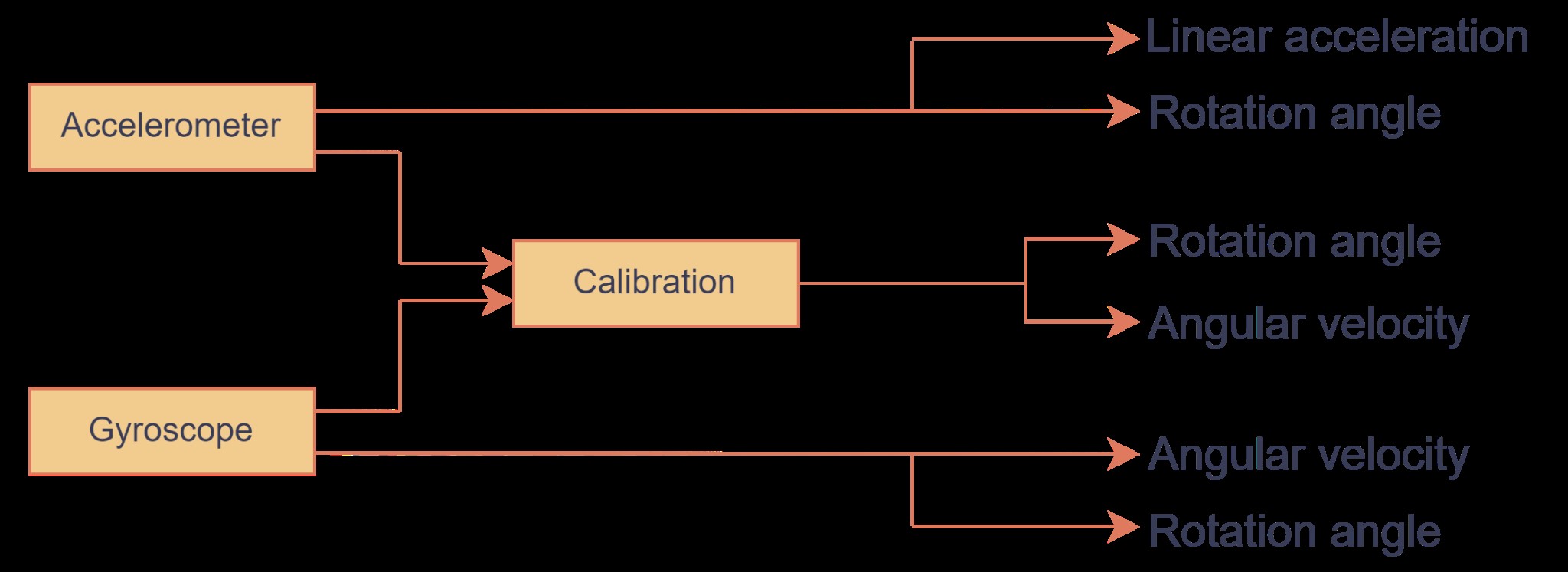
Figure 2. IMU based on two types of sensors [23]
4.1.3 Modeling and Prototyping
3D modeling and simulation are critical for visualizing the robots design, testing mechanical interactions, and predicting performance before physical construction. CAD software, such as SolidWorks, will be utilized to create detailed 3D models of the robot, encompassing all mechanical components, electrical layout, and mounting points. The model will be iteratively refined based on simulation feedback, with design adjustments to the chassis, component placement, and support structures made in the software before constructing the physical prototype. The simulation will test the robots ability to navigate and avoid obstacles in virtual environments, enabling design modifications before physical assembly.
Starting with assembling the chassis, attaching the motors, wheels, caster balls, fitting all parts together as designed. Then, carefully route and connect all electrical components, including the battery, Raspberry Pi, Cricket Hat and sensors. It is important to organise the wiring to avoid interference and ensure easy maintenance. To test and troubleshoot the initial design of the robot, perform a power-on test to check that all components receive power and communicate with each other correctly. Diagnose and fix all issues that arise during assembly and ensure that all components are securely attached and functioning. After the prototype is complete, prepare the robot for the experimental setup and testing phase.
4.2 Software Development and Integration
4.2.1 Topological Mapping Algorithm Adaptation
The project will leverage the topological mapping algorithm developed by Chew Jing Wei, as detailed in their final year project report. This algorithm offers a robust approach to generating topological maps from occupancy grid maps, even in the presence of noise. [24] This project will modify the topological mapping algorithm which is excellent at managing noisy occupancy grid maps and precisely extracting important topological features. It uses targeted obstacle expansion to minimise noise, a thinning algorithm to extract topological lines and a new transition-based technique for accurate node extraction, even from lines that are not one pixel wide. Additionally, it also includes pruning for semantic node identification representing distinct spaces and a distance transform-based method for identifying nodes representing distinct spaces.
[24] The adaptation process will concentrate on integrating data from the robots Lidar and IMU sensors, possibly utilising sensor fusion techniques. [29] Furthermore, the algorithm will be utilised for real-time performance on the Raspberry Pi, involving code profiling and algorithmic enhancements. Experimental parameter tuning will be conducted to determine the optimal thresholds for noise reduction, obstacle expansion and semantic node extraction, ensuring the algorithms effectiveness in real-world scenarios.
4.2.2 ROS Implementation
Since the existing algorithm has not been packaged for ROS, it will be encapsulated within a new ROS package, adhering to the standard ROS package layout, including directories for source code, launch files, configuration files, and documentation. [25] The algorithms code will be refactored to conform to ROS conventions, utilising ROS message types for data exchange and incorporating ROS services for interacting with other nodes. The core algorithm which is the topological map generation will be implemented as a ROS node within the package, and subscribe to sensor data topics to process the data and publish the generated topological map. Then, launch files need to be created to conveniently start the necessary nodes and configure their parameters.
Interfaceingthe pre-existed of custom-developed ROS nodes with the Lidar and IMU sensors and gathering the raw sensor data and publishing it to designated ROS topics ensure a standardized and accessible data stream for subsequent processing. Additionally, leveraging packages like Adaptive Monte Carlo Localization (amcl) can help to estimate the robots pose within the generated map and continuously track the robots location. ROS allows visualization with the rviz tool. [25] It provides a real-time visual representation of the generated topological map, the robots position, sensor data streams and planned path. The visualization can help in monitoring the robots performance, understanding its perception of the environment, and debugging any potential issues.
4.3 Experimental Setup and Testing
4.3.1 Data Collection
Data collection focuses on gathering sensor data essential for validating the robot's navigation and map generation. The robot will be operated in a controlled indoor environment with predefined obstacles. During operation, data from the Lidar, IMU, and encoders will be continuously recorded. The Lidar provides distance measurements to surrounding objects, while the IMU captures the robots orientation and movement dynamics. The encoders track the robots wheel rotations, contributing to odometry calculations. All sensor data will be time-stamped and stored in ROS bags. The raw data will be preprocessed, including filtering and synchronization to remove noise. Low-pass filter to remove high-frequency IMU data and median filter to remove outliers and noise for Lidar data.
4.3.2 Data Fusion
Data fusion integrates multiple sources of data to produce more accurate, reliable, and comprehensive information than could be achieved by processing each data source individually, the process of data fusion is shown in Figure 3. The preprocessed Lidar data is used for scan matching, key features are identified in all scans, providing an estimate of the robot's movement by comparing consecutive scans. The alignment process of two consecutive scans finds the optimal match between corresponding features in the two scans. Algorithms Iterative Closest Point (ICP) and Normal Distributions Transform (NDT) can be used to achieve the alignment. [28] The final output of scan matching is an estimation of the robots movement, described in terms of how far and in what direction the robot has moved and how much and in what direction the robot has rotated.
The Kalman filter is then applied to the IMU data and combined with encoder data to estimate the robots position and orientation. The Kalman filter predicts the next state of the robot based on the previous state and control input. The filter then corrects this prediction by incorporating the new IMU measurements, reducing the error in the position and orientation estimates. [27] After obtaining the odometry estimation from the Kalman filter, the result is fused with the result of scan matching. [29] The Kalman filter continuously updates the fused estimate by considering the uncertainties in both the scan matching and odometry data. [30]
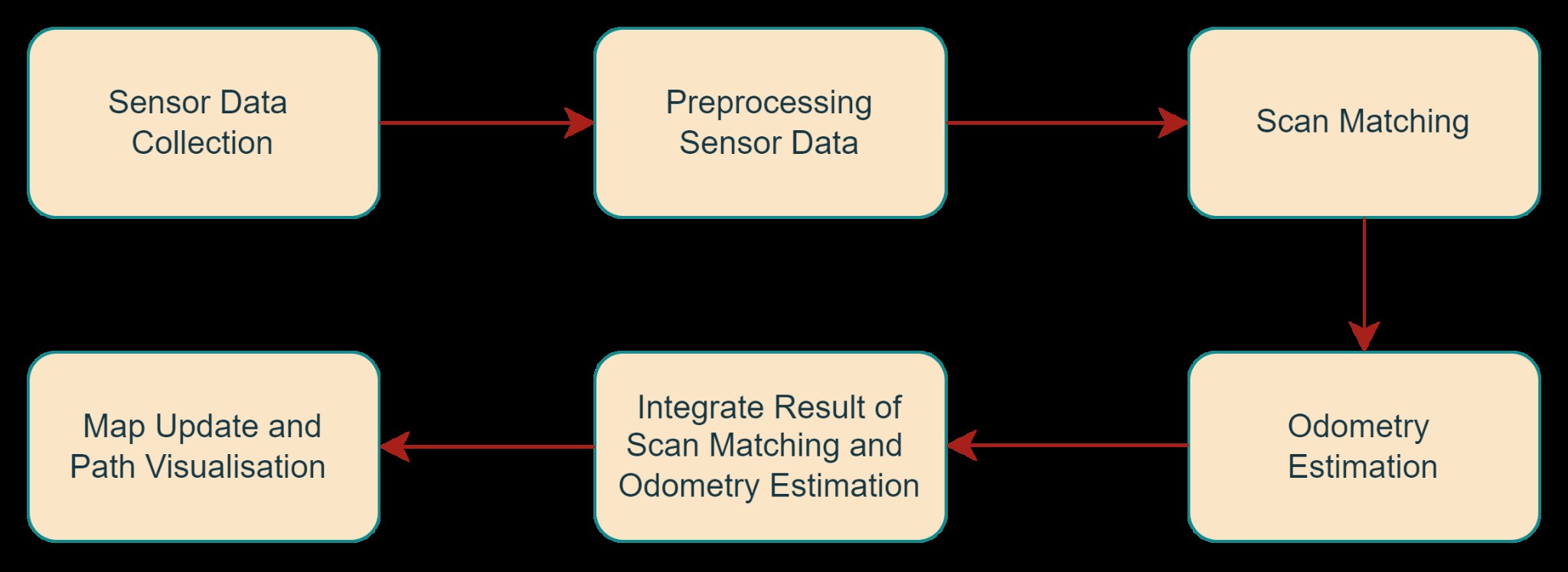
Figure 3. Data fusion process
4.3.3 Map Validation
Map validation will involve comparing the map generated by the robot with a reference map of the environment. The reference map, created using the pre-existed algorithm, serves as the benchmark for accuracy. The generated maps key features, such as node positions and connectivity, will be analyzed against the reference. Metrics like node matching accuracy, edge consistency, and overall map structure will be evaluated. Any discrepancies between the generated and reference maps will be examined to identify and rectify potential sources of error in the mapping process.
5.Scope, Project Plan & Timeline
5.1 Project Scope
In-Scope
- Design and construct a mechanical robot with various sensors
- Adapt and integrate an existing topological map generation algorithm into the hardware
- Test and validate the path navigated by the robot with the topological map generated by the
Out-of-Scope
- Improve and optimize the existing topological map generation
Limitations/Constraints
- The project timeline is limited by external factors such as semester deadlines or other academic commitments, which may restrict the extent of algorithm optimization and testing.
- Sensor limitations such as 2D LiDAR sensors have a limited field of view and may struggle in environments with complex 3D structures or highly reflective surfaces.
- The robot's performance may be affected by factors such as lighting conditions, sensor noise, and dynamic obstacles in the environment.
5.2 Project Plan & Timeline
Gantt chart is a visual aid for project management that shows milestones, timeframes, and activities for the project. It offers a concise and organised summary of all project tasks, along with information on their beginning and ending dates and interdependencies. Figure 4 and Figure 5 demonstrate the Gantt chart.

Figure 4. Gantt chart of Semester 2 2024, FYP A
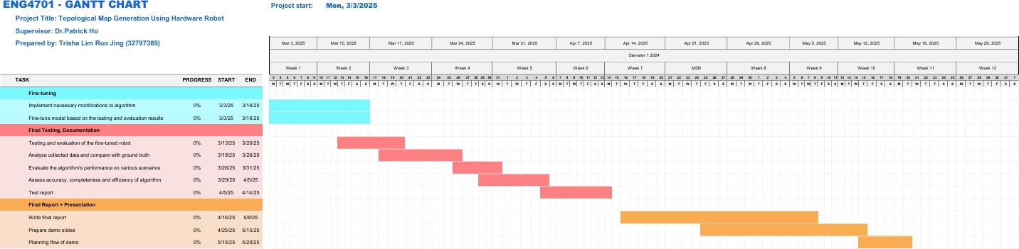
Figure 5. Gantt chart of Semester 1 2025, FYP B
The project timeline for the "Topological Map Generation Using Hardware Robot" is broken down into two parts which are FYP A and FYP B and several key phases. FYP A begins with preparing the Project Proposal Report, where the introduction, aims, objectives, literature review, methodology, project scope and risk management plan are developed in sequence. Next, the Robot Design and Construction phase involves budgeting, purchasing items, testing sensors, assembling the robot mechanically and integrating electronics and sensors. This phase lays the foundation for the robots physical structure and functionality.
The following is the Algorithm Adaptation phase. Here, the existing algorithm is reviewed and modified to work with the robot sensors, and implemented in ROS, ensuring that the software and hardware components are aligned. After the robot integration, Testing and Initial Evaluation follow, where the robot is tested in controlled environments, real-world data is collected, and the data is analysed and evaluated to assess the performance of the robot. At the same time, the Project Progress Report is prepared together. This phase involves drafting various sections of the report which include the introduction, methodology, results, discussion, conclusion and risk analysis.
For FYP B, the first task in the Fine-Tuning phase involves making necessary modifications to the algorithm based on previous tests and results to optimize the accuracy of the map generated by the robot compared with the input map. Then is the Final Testing and Documentation which tests and evaluates the robot performance in various scenarios and documents the findings and results in a test report. The last phase is the Final Report and Presentation. This phase is to write the final report to summarize the entire project and prepare to present and demonstrate the projects findings and achievements.
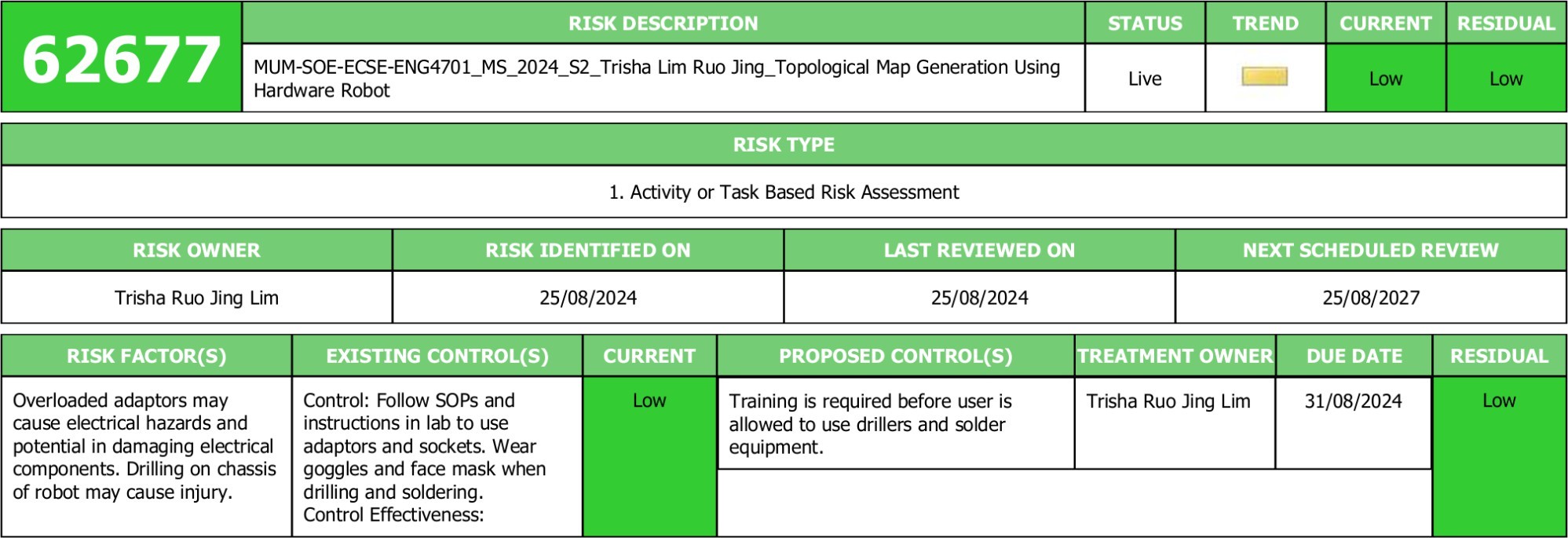
6. Risk Management Plan
Table 1 provides an overview of the risk assessment for non-OHS (Occupational Health and Safety) in this project. Other than that, OHS risks in this project are also attached to this report in Appendix A.
Table1: Risk Assessment Table for non-OHS Project Risks
Project Risk |
Risk |
Likelihood |
Consequence |
Risk Level |
Mitigation |
Residual Risk |
Robot Construction |
Mechanical failure or instability during robot operation. |
Possible |
Major |
H |
Ensure rigorous testing of mechanical components, use high-quality materials, and conduct multiple iterations of design and testing. |
Mechanical issues may still arise due to unforeseen circumstances, requiring additional adjustments or repairs. |
Sensor Malfunction |
Lidar and IMU sensors fail to provide accurate data. |
Unlikely |
Minor |
L |
Calibrate sensors thoroughly before deployment, and incorporate error-checking algorithms. |
Inaccurate sensor data may still occur, requiring recalibration or sensor replacement. |
Navigation Failure |
Robot fails to navigate according to the generated map. |
Possible |
Moderate |
M |
Integrate robust navigation algorithms, perform thorough testing in varied environments, and include manual override capabilities. |
Navigation issues may still occur, requiring real-time adjustments or manual intervention. |
Battery Drain |
Robot runs out of power during operation. |
Possible |
Moderate |
M |
Monitor battery levels continuously, use energy-efficient components, and provide easily accessible charging options. |
Power issues may still disrupt operation, necessitating a contingency for rapid battery replacement or recharge. |
Data Logging Failure |
Path data is not recorded accurately. |
Possible |
Major |
H |
Implement reliable data logging systems with backup storage, and test the system rigorously before deployment. |
Data loss or corruption may still occur, requiring data recovery procedures. |
Software Integration |
Issues with integrating hardware and software components. |
Possible |
Major |
H |
Follow systematic software development practices, perform incremental integration, and thoroughly test each integration step. |
Integration issues may still arise, requiring debugging and potential redesign of interfaces. |
Communication Failure |
Issues with communication between robot components or with the control system. |
Unlikely |
Moderate |
M |
Use reliable communication protocols, test for interference, and implement fallback communication methods. |
Communication issues may still occur, requiring manual intervention or system resets. |
Robot Damage |
Physical damage to the robot during testing or operation |
Unlikely |
Moderate |
M |
Implement protective casing, use durable materials, and conduct tests in controlled environments. |
Damage may still occur, necessitating repairs or component replacement. |
Schedule Delays |
Project milestones are not met on time |
Likely |
Moderate |
H |
Develop a detailed project timeline with buffers, monitor progress regularly, and adjust schedules as needed. |
Delays may still happen, requiring contingency planning and potential scope reduction. |
7. Appendices
- Appendix A: Project Risk Assessment