Automatic Wire Cutter Assignment
- Country :
Australia
3.1 INTRODUCTION
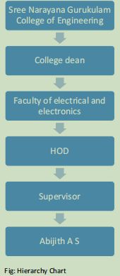
This project was carried out for completing my B tech degree in Electrical and Electronics Engineering from Sree Narayana Gurukulam College of Engineering. It is located in Kadayiruppu, India. It dated from January 2015 to April 2015 and was performed by me alone under the guidance of Assistant Professor, Aswathy Mohandas P.
3.2 BACKGROUND
3.2.1 The manual task of wire measurement and cutting of measured length is time consuming and can cause injuries to the workers. The use of automatic wire cutters can significantly decrease the effort as well as time for performing several tasks of project works as the automatic wire cutter is capable for measuring, striping and cutting wires on the basis of specification of the wire which is exactly similar to manual operation.
3.2.2 This project is based on the development of an automatic wire cutter. The physical action is replaced by this device as the user can simply place wire and provide suitable setting to device which can measure strip and cut the wire in precise manner.
3.2.3 Developing an automatic wire cutter is the major aim of this project which is also followed by other objectives like:
- To provide safety to the workers from injuries that can be caused by using traditional wire cutting technique.
- To improve companys quality and productivity by reducing processing time and cost with the use of the automatic wire cutter.
3.2.4 Then I made a flow chart for overall working of the project and wrote the Arduino code in Arduino IDE software by using simplified C++ language.compiled the code and obtained a .hex file. I made PROTEUS circuit by placing each of the circuit components as per the proposed design and uploaded the .hex file in the Arduino block of PROTEUS software and simulated the layout for ensuring the proper operation of system. I manually provided the number and length of wire and confirmed the data and count the number of rotation of motor and calculated the total length covered by the motor which was shown in 16x2 LCD display
3.2.5 My task throughout the project were:
- I researched some related matters and reviewed some related past projects.
- I prepared the proposed systems block flow diagram which highlighted major components and system operation.
- I constructed a circuit diagram including all the necessary components.
- I coded a program in arduino and prepared a flow chart showing overall working of the project.
- I simulated the code and prepared its hardware model which was further tested for its performance.
3.3 PERSONAL ENGINEERING ACTIVITY
3.3.1 In the beginning, I traced out the literary works of several papers and previous works related to the project from which I gained knowledge about the overview and working mechanism of automatic wire cutting system. I also studied about the required components as well as their operation in this projects.
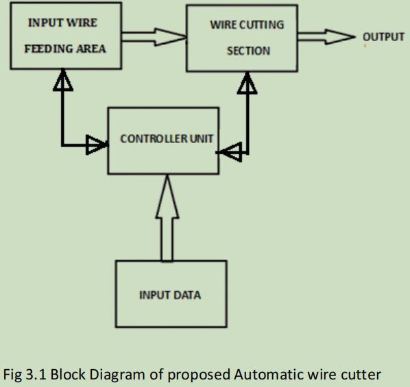
3.3.2 After that, I made a block flow diagram of the proposed system. I included the wire feeding section, input setting section, controller section and wire cutting section in the block diagram with the functional operation which could give the required output.
3.3.3 After that I constructed a circuit diagram which included an Arduino, L293DE motor driver,dc motors,bush buttons, LCD display,infrared sensor etc. Here I used Arduino as controlling unit, two motors for driving the wire towards cutting blade, one motor for moving cutting blade, L293DE motor driver for controlling motor operation,three push buttons for increasing, decreasing and confirming the adjustment of desired length and number of wire, an infrared sensor for measuring rotation of wheel to calculate the length of wire and a LCD display to show the system operation.

3.3.4 Then I made a flow chart for overall working of the project and wrote the Arduino code in Arduino IDE software by using simplified C++ language.compiled the code and obtained a .hex file. I made PROTEUS circuit by placing each of the circuit components as per the proposed design and uploaded the .hex file in the Arduino block of PROTEUS software and simulated the layout for ensuring the proper operation of system. I manually provided the number and length of wire and confirmed the data and count the number of rotation of motor and calculated the total length covered by the motor which was shown in 16x2 LCD display.
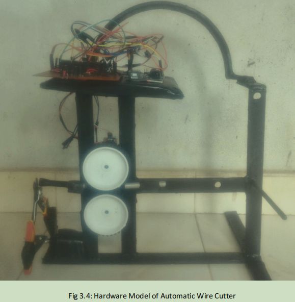
3.3.5 After the successful operation in simulation, I made an experimental arrangement in breadboard for the practical verification and fabricated PCB circuit which was designed by using PCB Wizard. For this, I connected the circuit similar to the circuit made in PROTEUS simulation. I constructed the hardware model of motor operation and wire cutting mechanism. Then I tested the overall system of automatic wire cutting. I provided the input number of wire and length and then placed a wire. Then two motor arrangement dragged the wire towards the wire cutter and after reaching the provided length, the third motor operated the wire cutter to cut the wire.

3.4 TECHNICAL PROBLEMS AND SOLUTIONS
3.4.1 Problem in motor operation
During the hardware development of project, I felt the difficulty in motor operation. During the simulation, I connected dc motor to Arduino directly through a relay. The virtual simulation of dc motor was done in normal conditions. But when I proceed to the realization of the PROTEUS circuit, I felt difficulties in the motor operation. I selected the dc motor of voltage ratings of 6 V and operated the motor directly. But the issue which aroused was uncontrolled direction of rotation of two parallel motors which dragged the wire in. Then I consulted with my supervisor and conducted several team meetings for discussing the issues. After going through several discussions and searching in internet, I found the best method of using motor driver to drive the motor. Then I employed L293DE motor driver which can provide the controlled operation of driving the motor in both direction. The motor controller provide the clockwise and anticlockwise operation of the motor from the logic 10 and 01 in the input pins of driver whereas stops the motor operation by providing logic 00 or 11. After implementing the motor driver, I tested the system and found that the motor operation was fine.
3.4.2 Difficulty due to false calibration of IR sensor
The next difficulty that I coped with in this project was about the calibration of IR sensor range. During the hardware model implementation of the system, the range of the IR sensor created an issue. I used an IR sensor for detecting and measuring the number of rotation of motor so as to calculate length of the wire. When I tested the system, I specified wire length of 25 cm. But the IR sensor could not sense any movement of motor and the LCD display showed zero rotation even when there was continuous operation of the wire driving motor and hence there was not any cutting operation by the wire cutter. I felt that this issue was due to the short range of IR sensor. Then I adjusted the preset of IR sensor module for slight increasing the range of IR sensor. After increasing range, I tested the range of IR sensor to confirm that the module could sense the rotation of motor wheel or not. After the verification, I placed the IR sensor and tested the hardware model with same initial condition. I provided the input wire length and initiated the system. This time, I observed the counting of number of rotation of motor and calculation of length in LCD display.
3.4.3 Problem due to wrong wire length measurement
Another problem which was encountered in this project was due to the length measurement of the wire. After the construction of the hardware model, I provided the input wire length of 25 cm and initialized the system. After the completion of cutting process, I measured the length of wire for the verification of accuracy of device. During the measurement, I found that the length of the wire was 40 cm. This was the huge problem as the accuracy of the cutting device was out of the acceptable range. Then I investigated the main reason for occurring this issue and possible solution that can be taken into action for mitigating this problem. After several searches in internet sources and discussions with my team members, I decided to review the program code to operate the motor as more numbers of turns had led to the longer length of the wire. During the inspection of the code,
I found the proper calculations and calibration of the length of wire and number of rotation. Then I moved ahead for inspection of the hardware model and I found that there was variation in the dimension of rotating wheel of motor in the hardware model and program code. Then I recalculated the number of rotation required for the motor wheel to cover a unit length and then modified in the code. Then I uploaded the modified code in Arduino and then evaluated the accuracy of performance. This time the system was able to cut the wire exactly as per the provided length.
3.5 CREATIVITY
I creatively prepared flowchart and made program code in Arduino software by using simplified C++ programming language. I used the motor driver for proper controlling and operation of dc motor. I calibrated the range of IR sensor to adjust the range for detecting the rotation of motor wheel and calculated the corresponding length of wire.
3.6 TEAM COORDINATION AND PROJECT MANAGEMENT
This entire project was concluded by me alone which added pressure of finishing the work within given time. This encouraged me to adopt effective project plan which was done by enlisting project activities and distributing specific time to each activities. I included these criteria in a Gantt for a proper representation. I consulted with my seniors as well as supervisor to get solutions regarding issues during this project. I prepared a daily report showing everyday work and results.
3.7 CODES AND STANDARDS
I used ISO 29.100.10 and ISO 35 160 for selecting general electronic components and integrated circuits.
3.8 SUMMARY
3.8.1 The proposed design was successfully designed and developed which showed high performance on testing and ensured concerned safety. This work was based on providing benefits to the company regarding its employees safety, cost control, low working risks, etc.
3.8.2 After researching related matters, I prepared a block diagram highlighting all the major components and operation of the design. I constructed a circuit diagram and coded a program in Arduino. After proper simulation of the code, I created a hardware model of the design and carried out further testing.
3.8.3 The project was completed achieving all the goals highlighted above. A final report was prepared by accumulating all the details of my work throughout the project and was presented to the college faculty.
Are you struggling to keep up with the demands of your academic journey? Don't worry, we've got your back! Exam Question Bank is your trusted partner in achieving academic excellence for all kind of technical and non-technical subjects.
Our comprehensive range of academic services is designed to cater to students at every level. Whether you're a high school student, a college undergraduate, or pursuing advanced studies, we have the expertise and resources to support you.
To connect with expert and ask your query click here Exam Question Bank
