CVE10007 Assembly, tolerance and die mold design Assignment
- Subject Code :
CVE10007
-
Instructions:
This third task includes three parts:
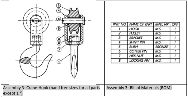
1- Part one: Make an assembly composed of the numbered parts for each drawing below. Item numbers are given for each assembly to show the different parts clearly.
2- Part two: Tolerances in manufacturing and 3D printing
3- Part three: Design Plastic injection die mold (Links to an external site.) for one chess piece chosen from the provided parts Download the provided parts
Submission:
Make Pdf drawings of each part with title block and fill in the information including mass of the part in grams in the drawing
Keep in mind this task is the last part of your Design Portfolio, submit as part of your portfolio.
- Make sure to submit both native file and their pdfs (merged pdf for drawings and archived zip for native files)
1.1 Part one-Assemblies to be constructed
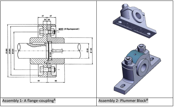
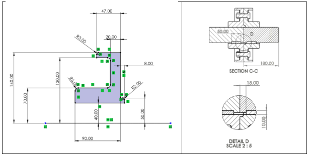
Assembly 1: Each shaft is 180mm long and the keyway dimensions are 5x5x50mm which starts 15mm from top of the shaft. Each shaft head is flush with the flanges flat face.
Use following sketchs:
Use the hook from your task 2, Part 5, and make the rest of parts to fit the hook in a free hand fashion. You may want to use the following sizes just as a basic guide. You can assume the missing sizes as long they allow a reasonable part/assembly.

Only key dimensions are provided, for other dimensions, assume a reasonable (or commercially available stock size).

1.2 Part two: Tolerances in manufacturing and 3D printing
- CVE10007, Engineering Design and Innovation
- Shahin Khoddam, Convenor
- Bernie Koziol, lab instructor
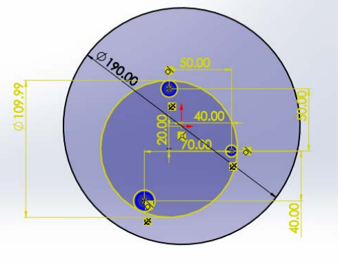
A disc plate has three pins on it as shown in Figure 1:

Basic dimensions of the disc and the locations of the centres for the three pins are given in Figure 2:
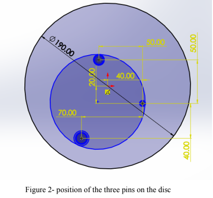
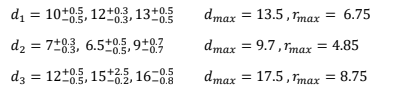
The same disc has been manufactured by several manufacturers in different countries, however, the pin diameters are slightly different based on their manufacturers. The variations in the pin diameters have been given as:

2. The design tasks
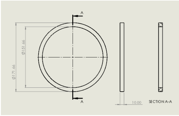
2.1 Design two ring spacers that fulfills the following requirements:
Ring specifications and needs:
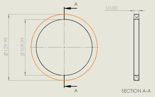
a- Two spacers are to be designed, concentric (about the centre of disc) and non-concentric(enveloping the three pins only)
b- 10mm radial thickness
c- 10mm height
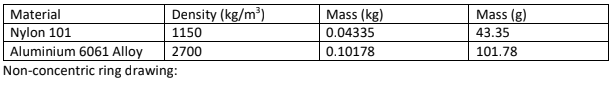
d- Two rings are to be designed with the following materials:
- Nylon 101
- Aluminium 6061 alloye
e. Fits all three variants easily with the following conditions
Mass:
a. Concentric with the disc: less than: Mass = 58.41 grams (Nylon 101)
b. Non-concentric with disc: less than: Mass = 43.35 grams (Nylon 101)
2.2 Laboratory validation of the design
Make a 3D model of the concentric and non-concentric spacers (rings) and 3D print them
in TD320
Your 3D printed designs should fit some of the existing manufactured 3Pins discs.
Three attempts are permitted before you get a score for the lab.
Also, the mass of each ring will be measured and should comply with the specified needs.
Part 3: Design die-cast mould for one chess
piece chosen from the provided parts
For a general understanding of the die-cast moulding, watch the following video:
Apply proper shrinkage for a PET part to be injected (account for dimension changes due to shrinkage in the moulds cavity)
1. Choose the parts plane of symmetry as the moulds separation plane
King
Queen
Knight
Rook
Pawn
2. 3D Print your designed mould and verify your design with the existing parts in the
TD320 by checking its fit with the part.
3. The solutions:
We make 3D models of the disc with the worst scenario (maximum diameters). These are shown in
Fig. 3


Concentric drawings: